
Low-speed large-torque hydraulic oil cylinder motor for oil pumping unit

A hydraulic cylinder and high-torque technology, applied in the direction of fluid pressure actuators, etc., can solve the problem of low transmission efficiency of the pumping unit drive system, achieve the effect of simple maintenance and improved transmission efficiency

Inactive Publication Date: 2021-01-29
郭家朋
View PDF0 Cites 0 Cited by
  • Summary
  • Abstract
  • Description
  • Claims
  • Application Information

AI Technical Summary

Problems solved by technology

[0003] The purpose of the present invention is to provide a low-speed high-torque hydraulic cylinder motor for pumping units to solve the problem of low transmission efficiency of the pumping unit drive system in the prior art

Method used


Image

  • Low-speed large-torque hydraulic oil cylinder motor for oil pumping unit

Examples


Embodiment Construction

[0012] The present invention will be further described below in conjunction with the accompanying drawings and embodiments.

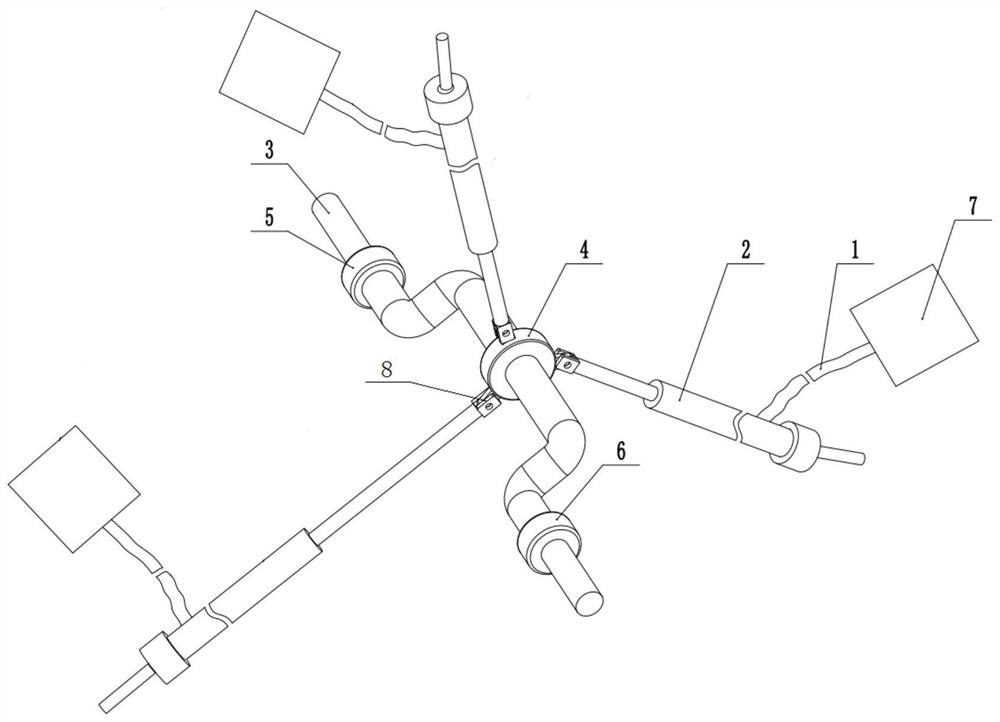
[0013] like figure 1 As shown, a low-speed high-torque hydraulic cylinder motor for a pumping unit includes an axially horizontal crankshaft 1. The middle section of the crankshaft 1 is a straight shaft. The two ends of the crankshaft 1 are respectively bent downward and then horizontally respectively. This forms the crankshaft structure, and the middle position of the middle section of the crankshaft 1 is coaxially fixed with an articulation disc 4 .

[0014] It also includes three linear push-pull drive mechanisms distributed around the hinged disk, and the three linear push-pull drive mechanisms are evenly distributed in the ring direction. Each linear push-pull drive mechanism includes a hydraulic cylinder 2 respectively, and the hydraulic cylinders 2 are respectively connected to the corresponding hydraulic control system 7 through oil pipes. 8 i...


PUM


Abstract

The invention discloses a low-speed large-torque hydraulic oil cylinder motor for an oil pumping unit. The motor comprises a crankshaft, a hinge disc is coaxially fixed to the middle of the crankshaft, and the ends of moving parts in a plurality of linear push-pull driving mechanisms are hinged to the disc edge of the hinge disc. The whole transmission efficiency is improved, and the beneficial effect of being easy to maintain is achieved.

Description

technical field [0001] The invention relates to the field of pumping unit motors, in particular to a low-speed and high-torque hydraulic cylinder motor for a pumping unit. Background technique [0002] At present, the drive system of the pumping unit is: 8-pole 750-rpm or 6-pole 1000-rpm motor drives the pulley, and drives the reducer through the belt drive. The reducer has double output shafts, which output low-speed and high-torque, and then drive the pumping unit connecting rod up and down. The movement drives the donkey head, and finally drives the pumping unit to move up and down. Because this drive system has two stages of reduction: belt and reducer, especially the efficiency of belt reduction is low, so the overall system efficiency is low. It is difficult and uneconomical to maintain the belt and reducer outdoors. Contents of the invention [0003] The object of the present invention is to provide a low-speed high-torque hydraulic cylinder motor for a pumping un...

Claims


Application Information

Patent Timeline
Patent Type & Authority Applications(China)
IPC IPC(8): F15B15/06F15B15/20
CPCF15B15/06F15B15/20
Inventor 郭家朋
Owner 郭家朋
Learn More