
Calibration method for force sensor

A technology of force sensor and calibration method, applied in the field of sensors, can solve problems such as inaccurate calibration of force sensor

Inactive Publication Date: 2021-01-29
深圳市鑫精诚科技有限公司
View PDF13 Cites 0 Cited by
  • Summary
  • Abstract
  • Description
  • Claims
  • Application Information

AI Technical Summary

Problems solved by technology

[0004] The purpose of the present invention is to provide a force sensor calibration method, aiming to solve the problem that force sensor calibration is not accurate enough in the prior art

Method used


Image

  • Calibration method for force sensor
  • Calibration method for force sensor

Examples


Embodiment Construction

[0016] In order to make the object, technical solution and advantages of the present invention clearer, the present invention will be further described in detail below in conjunction with the accompanying drawings and embodiments. It should be understood that the specific embodiments described here are only used to explain the present invention, not to limit the present invention.

[0017] In the drawings of this embodiment, the same or similar symbols correspond to the same or similar components; The indicated orientation or positional relationship is based on the orientation or positional relationship shown in the drawings, and is only for the convenience of describing the present invention and simplifying the description, rather than indicating or implying that the referred device or element must have a specific orientation, or in a specific orientation. Construction and operation, so the words describing the positional relationship in the drawings are only for illustrative...


PUM


Abstract

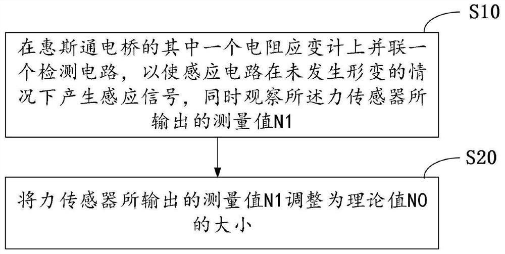
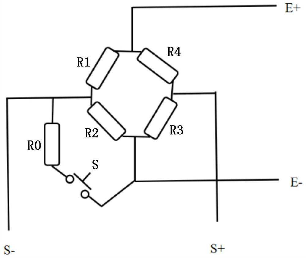
The invention relates to the technical field of sensors, and discloses a calibration method for a force sensor. The force sensor comprises an induction circuit which can generate an induction signal according to the deformation degree. The calibration method comprises the following steps that a calibration circuit is connected to one resistance strain gauge of the Wheatstone bridge in parallel, sothat the induction circuit generates an induction signal under the condition that deformation does not occur, and meanwhile a measurement value N1 output by the force sensor is observed, wherein under the condition that the resistance value of the calibration circuit is known, the theoretical value output by the force sensor is N0; and the measured value N1 output by the force sensor is adjustedto be the theoretical value N0. According to the calibration method for the force sensor provided by the invention, the force sensor can be calibrated under the condition of simulating full-scale output by accurately controlling the resistance value of the calibration circuit, so that the calibration error can be effectively reduced, the calibrated sensor is more accurate, and great convenience isbrought to production work.

Description

technical field [0001] The invention relates to the technical field of sensors, in particular to a force sensor calibration method. Background technique [0002] A force sensor is a device that can sense a force signal and convert the force signal into an electrical signal or other signal output. It is widely used in power equipment, construction machinery, industrial automation systems, and human-computer interaction systems. For example, in the field of robotics, many devices are equipped with force sensors for mechanical feedback for human-computer interaction control. [0003] In practical applications, due to various reasons, such as the deviation of the force sensor itself, different equipment for installing the force sensor, and different operating environments, it is easy to cause errors between the indicated value (that is, the measured value) of the force sensor and the actual value to be measured. , so calibration is required. However, in the prior art, due to t...

Claims


Application Information

Patent Timeline
Patent Type & Authority Applications(China)
IPC IPC(8): G01L25/00
CPCG01L25/00
Inventor 韩学荣吴美贞孙建龙徐进
Owner 深圳市鑫精诚科技有限公司
Learn More