Display module

A technology for display modules and display panels, which is applied to housings with display/control units, identification devices, instruments, etc. It can solve problems that affect the bending reliability of the binding area and affect the adhesion, so as to improve the adhesion , the effect of improving reliability

Active Publication Date: 2021-01-29
WUHAN CHINA STAR OPTOELECTRONICS SEMICON DISPLAY TECH CO LTD
View PDF30 Cites 34 Cited by
  • Summary
  • Abstract
  • Description
  • Claims
  • Application Information

AI Technical Summary

Problems solved by technology

[0005] The embodiment of the present invention provides a display module to solve the problem that in the existing display module, in order to realize narrow frame and ultra-thin module design, it is necessary to design the bending radius of the bending area to be small, that is, it is necessary to reduce the bending radius. The height of the bending area is generally achieved by reducing the thickness of the reinforcement plate, but the thinner thickness of the reinforcement plate will affect its adhesion, which in turn will affect the technical problem of the reliability of the bending of the binding area

Method used


Image

  • Display module
  • Display module
  • Display module

Examples


Embodiment Construction

[0023] The following descriptions of the various embodiments refer to the accompanying drawings to illustrate specific embodiments in which the invention may be practiced. The directional terms mentioned in the present invention, such as [top], [bottom], [front], [back], [left], [right], [inside], [outside], [side], etc., are only for reference The orientation of the attached schema. Therefore, the directional terms used are used to illustrate and understand the present invention, but not to limit the present invention. In the figures, structurally similar elements are denoted by the same reference numerals.

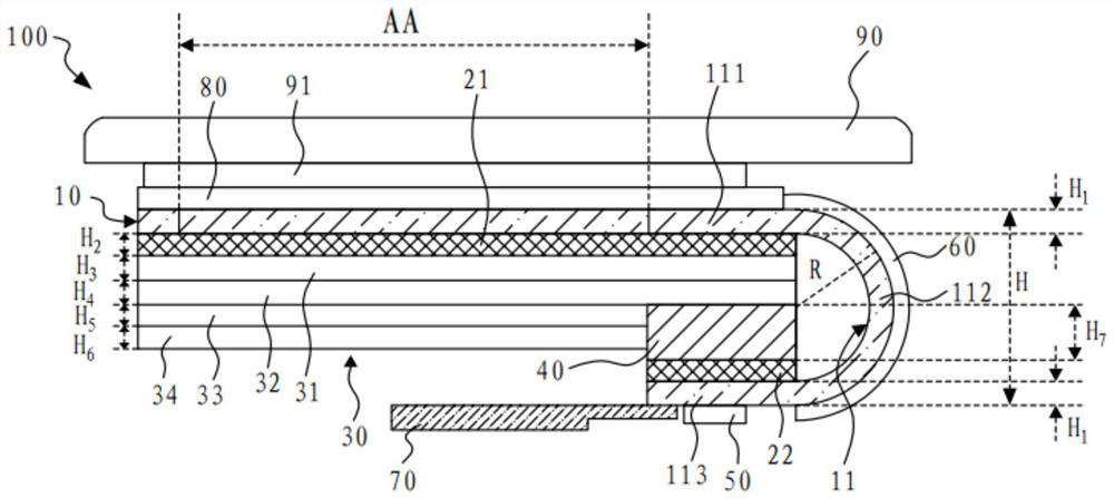
[0024] The present invention aims at the existing display module, in order to realize the narrow frame and ultra-thin module design, the structural design of the reinforcing plate is too thin, resulting in insufficient adhesion, which affects the technical problem of the bending reliability of the binding area , this embodiment can solve this defect.

[0025] see fig...


PUM


Abstract

The invention discloses a display module, which comprises a display panel, a first backboard, an SCF assembly and a reinforcing plate, wherein the display panel comprises a display area and a bindingend located on one side of the display area, the end, which is away from the display area, of the binding end is connected with a driving chip, and the binding end is bent towards the side deviating from a light emitting surface of the display panel, so that the driving chip is located on the side, which deviates from the light emitting surface, of the display panel; the first backboard is arranged on the side, which deviates from the light emitting surface of the display panel, of the display panel; the SCF assembly and the reinforcing plate are both arranged on the side, which deviates fromthe display panel, of the first back plate; and an accommodating groove is formed in the side, which deviates from the display panel, of the SCF assembly, at least part of assemblies of the reinforcing plate are accommodated in the accommodating groove, and the driving chip is located on the side, which deviates from the display panel, of the reinforcing plate.

Description

technical field [0001] The invention relates to the field of display technology, in particular to a display module. Background technique [0002] Display modules, as display components of electronic equipment, have been widely used in various electronic products, and the design of narrow bezel and ultra-thin modules is increasingly favored by terminal manufacturers and consumers. End consumers have increasingly stringent requirements on the size of the frame of the display module and the thickness of the display module. How to design a module structure with a narrow frame and ultra-thin thickness is an urgent problem to be solved. [0003] The implementation of the narrow bezel solution mainly depends on the bending of the binding area so that the driver chip is bent to the back of the display module. The back of the display panel in the existing display module is generally attached with a SCF (Super CleanFoam, ultra-clean foam) structure and a reinforcement plate. The SCF ...

Claims


Application Information

Patent Timeline
Patent Type & Authority Applications(China)
IPC IPC(8): G09F9/30G09F9/33
CPCG09F9/30G09F9/301G09F9/33H10K59/8794H10K77/111H05K5/0017H05K7/20954H10K50/87
Inventor 夏浩
Owner WUHAN CHINA STAR OPTOELECTRONICS SEMICON DISPLAY TECH CO LTD
Why Eureka
Try Eureka