Supercharge Your Innovation With Domain-Expert AI Agents!

Gas-liquid combined temperature control device

A technology of temperature control device and gas-liquid combination, which is applied in centrifuges and other directions, can solve problems such as temperature rise and affect the performance of electronic components, and achieve the effects of reducing pressure head, improving heat exchange capacity, and increasing heat exchange area

Pending Publication Date: 2021-02-02
POWERCHINA HUADONG ENG COPORATION LTD
View PDF0 Cites 0 Cited by
  • Summary
  • Abstract
  • Description
  • Claims
  • Application Information

AI Technical Summary

Problems solved by technology

The heat accumulates in the machine room, causing the temperature in the machine room to rise, which in turn affects the performance of electronic components such as measurement sensors in the machine room

Method used


Image

  • Gas-liquid combined temperature control device
  • Gas-liquid combined temperature control device

Examples


Embodiment Construction

[0014] The present invention will be further described below in conjunction with the accompanying drawings and specific embodiments.

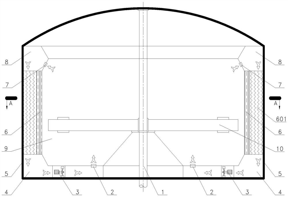
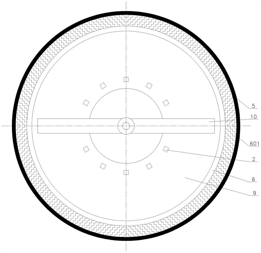
[0015] Such as figure 1 , figure 2 As shown, a gas-liquid combined temperature control device, the gas-liquid combined temperature control device is arranged in the host chamber 9 of the geotechnical centrifuge, and the gas-liquid combined temperature control device includes The air duct 8, the air outlet duct 4 arranged at the bottom of the main engine room 9 of the centrifuge, and the side wall heat exchanger 6 arranged on the inner wall of the main engine room 9, the side wall heat exchanger 6 is provided with heat exchange fins 601, and the air inlet The duct 8 communicates with the end of the air duct 4 close to the inner wall of the main machine room 9 through the heat exchange fins 601 .

[0016] One side of the side wall heat exchanger 6 facing the interior of the main engine chamber 9 is a smooth surface, and the other side of the s...


PUM


Abstract

The invention provides a gas-liquid combined temperature control device, aims to overcome the defects of a heat dissipation technology in a main machine chamber of a geotechnical centrifuge in the prior art, and fully utilizes an inner side liquid cooling wall and outer side air heat exchange fins of a heat exchange device to exchange heat with air in the main machine chamber on the premise of ensuring the smoothness of the inner side wall surface of the main machine chamber. Meanwhile, the temperature control device can operate in a vacuum state, the current situation that a side wall heat exchanger can only utilize the inner side to exchange heat with air and cannot utilize air cooling in the vacuum state is solved, and the heat exchange capacity of the temperature control device is integrally improved. The gas-liquid combined temperature control device is arranged in the main machine chamber of the geotechnical centrifuge and comprises an air inlet channel formed in the top of the inner side wall of the main machine chamber, an air outlet channel formed in the bottom of the main machine chamber of the centrifuge and a side wall heat exchanger, and the lower end of the air inletchannel communicates with the end, close to the inner side wall of the main machine chamber, of the air outlet channel through heat exchange fins.

Description

technical field [0001] The invention relates to the technical field of heat dissipation temperature control equipment, in particular to a heat dissipation temperature control device suitable for the field of geotechnical centrifuge engineering. Background technique [0002] During the high-speed operation of the geotechnical centrifuge, parts such as the rotating arm and the hanging basket rotate, which drives the air in the engine room to flow, causing relative motion between the rotating arm and the support, the rotating arm and the air, and the air and the wall of the machine room to generate heat. These heats accumulate in the machine room, causing the temperature in the machine room to rise, which in turn affects the performance of electronic components such as measurement sensors in the machine room. In order to reduce or even avoid such effects, in order to control the temperature rise of the machine room, a temperature control system must be designed to control the t...

Claims


Application Information

Patent Timeline
IPC IPC(8): B04B7/00B04B15/02B04B13/00
CPCB04B7/00B04B13/00B04B15/02
Inventor 颜加明黄维李成军郭德昌林志勇徐蒯东徐以洋郑传祥
Owner POWERCHINA HUADONG ENG COPORATION LTD
Features
  • R&D
  • Intellectual Property
  • Life Sciences
  • Materials
  • Tech Scout
  • Unparalleled Data Quality
  • Higher Quality Content
  • 60% Fewer Hallucinations
Learn More