A flange coding device and method

A flange and coder technology, applied in printing devices, power transmission devices, copying/marking methods, etc., can solve the problems of difficult to guarantee production quality, high labor intensity, and high labor cost, achieve accurate coding, improve The effect of production efficiency

Active Publication Date: 2022-07-05
GUANGZHOU WENCHONG SHIPYARD CO LTD
View PDF0 Cites 0 Cited by
  • Summary
  • Abstract
  • Description
  • Claims
  • Application Information

AI Technical Summary

Problems solved by technology

At this stage, manual coding is adopted for flange coding, and the flanges are coded one by one manually. During this process, the flanges need to be continuously transported to the coding machine. After the coding is completed, the flanges are placed on the pallet. Not only is the efficiency low, the labor intensity is high, and the production quality is difficult to guarantee; at the same time, manual coding requires many people to participate in the coding production process for a long time, and the labor cost is high
Nowadays, the ship construction cycle is shortened, and the requirements for ship construction efficiency are improved. Manual coding is difficult to meet the efficient ship production rhythm, and cannot adapt to the development trend of ship construction.

Method used


Image

  • A flange coding device and method

Examples


Embodiment 1

[0028] Embodiment 1: A flange coding device.

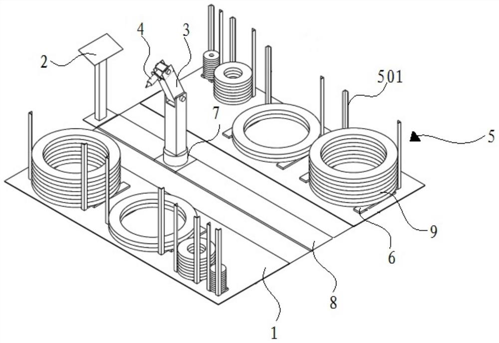
[0029] like figure 1 As shown, a flange coding device according to a preferred embodiment of the embodiment of the present invention includes: a platform 1, several storage racks 5, and a robot 3. The platform 1 is provided with a controller 2; each of the storage racks 5 are installed on the platform 1 for storing the flanges 9, the controller 2 can obtain the storage material level information of each of the storage racks 5, and the storage material level information includes the number of coded flanges and the number of unmarked flanges; the robot 3 is slidably installed on the platform 1, and the robot 3 is provided with a coder 4, and the robot 3 and the coder 4 are electrically connected to the controller 2 respectively. connected, the controller 2 controls the robot 3 to slide to the corresponding storage rack 5 , and then controls the coder 4 to code the flange 9 placed on the storage rack 5 .

[0030] Based on the above...

Embodiment 2

[0038] Embodiment 2: A flange coding method.

[0039] A flange coding method according to a preferred embodiment of the embodiment of the present invention is based on the flange coding device as described in Embodiment 1, and the specific steps of the method are as follows:

[0040] S1, the controller receives the coding and coding information sent from the external PC, matches the corresponding specification flange according to the coding and coding information, and detects whether the storage rack storing the corresponding specification flange has an uncoded flange;

[0041] S2, when it is detected that there is an uncoded flange, the controller sends a control signal to the robot, and the robot slides to the front of the corresponding storage rack and feeds back the signal to the controller;

[0042] S3, the controller receives the feedback signal from the robot and sends the control signal to the coder, and the coder identifies the uncoded flange and codes it;

[0043] S...


PUM


Abstract

The invention relates to the technical field of ship construction and production, and discloses a flange coding device and method. The coding device comprises: a platform, a plurality of storage racks, and a robot, and a controller is arranged on the platform; The material racks are installed on the platform for storing flanges; the robot is slidably installed on the platform, and the robot is provided with a coder, and the robot and the coder are respectively connected with the controller Electrical connection, the controller controls the robot to slide to the corresponding storage rack, and then controls the coder to code the flange placed on the storage rack. The invention abandons the traditional manual flange coding method, realizes fully automatic flange coding, greatly improves the production efficiency, and also ensures the quality of the flange coding.

Description

technical field [0001] The invention relates to the technical field of ship construction and production, in particular to a flange coding device and method. Background technique [0002] Before the flange and the pipe are assembled and welded in the ship construction process, the flange needs to be coded so that the pipe can be identified after galvanizing later. At this stage, the manual coding method is adopted for the flange coding, and the flanges are manually marked one by one. During this process, the flanges need to be continuously transported to the coding machine. After the coding is completed, the flanges are placed on the tray. Not only is the efficiency low, the labor intensity is high, and the production quality is difficult to guarantee; at the same time, manual coding requires many people to participate in the coding production process for a long time, and the labor cost is high. Nowadays, the ship construction period is shortened, and the requirements for sh...

Claims


Application Information

Patent Timeline
Patent Type & Authority Patents(China)
IPC IPC(8): B41J3/413B41J29/393B41J25/24B41M5/00
CPCB41J3/413B41J29/393B41J25/24B41M5/0058Y02P90/02
Inventor 苏士斌陈莉潘东向辉周柳英
Owner GUANGZHOU WENCHONG SHIPYARD CO LTD
Why Eureka
Try Eureka