Rear door locking device of movable household garbage horizontal compressor

A technology of domestic garbage and locking devices, which can be applied to garbage bins, garbage collection, household appliances, etc., and can solve the problems of falling to the ground, manual opening, increased workload, and ground damage.

Pending Publication Date: 2021-02-02
湖南坤鼎数控科技有限公司
0 Cites 0 Cited by

AI-Extracted Technical Summary

Problems solved by technology

[0004] The purpose of the present invention is: in order to solve the problem of using the current mobile household garbage horizontal compressor, after unlocking the lock, it needs to be manually opened to increase the workload; at the same ...

Method used

Please emphatically refer to Fig. 3 and Fig. 4, slide plate 31 is connected with shell 12 by rotating shaft, is convenient to slide plate 31 and shell 12 relative rotations, and the outer wall of connecting block 32 fits with the inwall of rope groove 33, is convenient to the outer wall...

Abstract

The invention discloses a rear door locking device of a movable household garbage horizontal compressor, and relates to the field of garbage compressors. The rear door locking device comprises a mainbody, a telescopic mechanism and a sliding mechanism, the main body comprises a base, the top end of the base is connected with a shell, one side of the shell is connected with a rear door, the outerwall of the shell is connected with a first electric push rod, the output end of the first electric push rod is located on the outer wall of the shell and connected with a lower door hook, and a fixing plate is fixed to the portion, located above the lower door hook, of the outer wall of the shell. By arranging a motor and starting the motor, the motor operates to drive a rotating shaft to rotate,the rotating shaft rotates to drive a rope disc to rotate, the rope disc rotates to enable a rope to extend out of a rope groove, a sliding plate is put down to make contact with the ground, garbageslides down along the sliding plate, and convenience is provided for the garbage to slide down along the sliding plate, so that the garbage smoothly slides down to the ground without directly fallingonto the ground and causing damage to the ground.

Application Domain

Refuse receptacles

Technology Topic

Slide plateDomestic waste +2

Image

  • Rear door locking device of movable household garbage horizontal compressor
  • Rear door locking device of movable household garbage horizontal compressor
  • Rear door locking device of movable household garbage horizontal compressor

Examples

  • Experimental program(1)

Example Embodiment

[0019]The technical solutions in the embodiments of the present invention will be clearly and completely described below in conjunction with the accompanying drawings in the embodiments of the present invention. Obviously, the described embodiments are only a part of the embodiments of the present invention, rather than all the embodiments. Based on the embodiments of the present invention, all other embodiments obtained by those of ordinary skill in the art without creative work shall fall within the protection scope of the present invention.
[0020]In the description of the present invention, it should be noted that the terms "center", "upper", "lower", "left", "right", "vertical", "horizontal", "inner", "outer", etc. The indicated orientation or positional relationship is based on the orientation or positional relationship shown in the drawings, which is only for the convenience of describing the present invention and simplifying the description, rather than indicating or implying that the pointed device or element must have a specific orientation or a specific orientation. The structure and operation cannot therefore be understood as a limitation of the present invention. In addition, the terms "first", "second", and "third" are only used for descriptive purposes, and cannot be understood as indicating or implying relative importance. In the description of the present invention, it should be noted that the terms "installation", "connection", "connection" and "setting" should be understood in a broad sense, unless otherwise clearly specified and limited. For example, they can be fixed connection or It can be a detachable connection or an integral connection; it can be a mechanical connection or an electrical connection; it can be directly connected or indirectly connected through an intermediate medium, and it can be the internal communication between two components. For those of ordinary skill in the art, the specific meaning of the above-mentioned terms in the present invention can be understood in specific situations. The embodiments of the present invention will be described below based on the overall structure of the present invention.
[0021]The motor (BWDOXWD2) mentioned in the present invention can be obtained from the market or privately ordered.
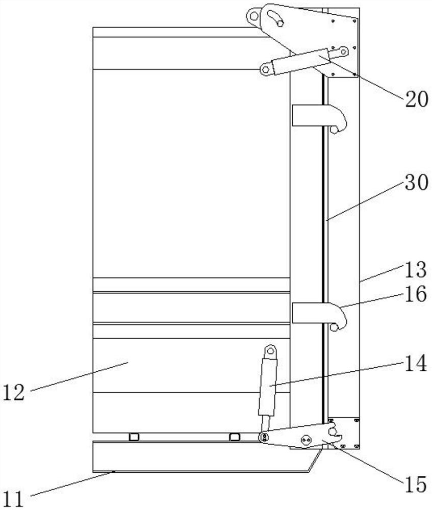
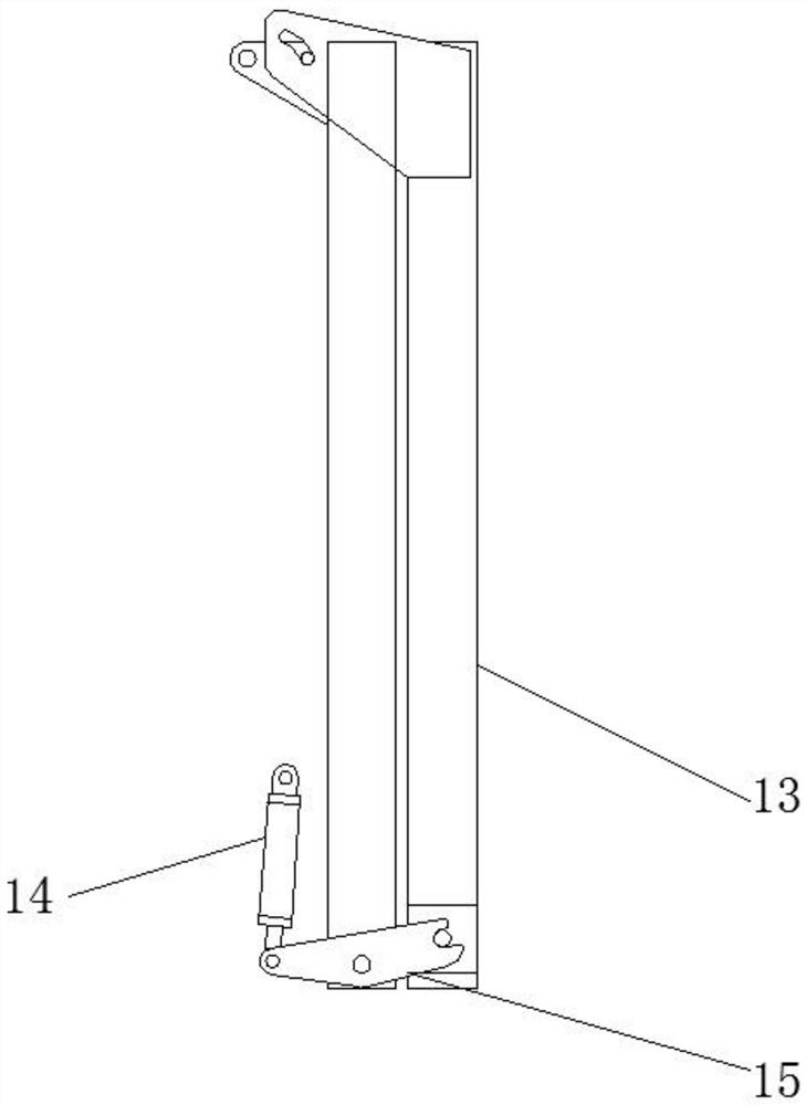
[0022]SeeFigure 1-4, A mobile domestic garbage horizontal compressor rear door locking device, including a main body, a telescopic mechanism 20 and a sliding mechanism 30. The main body includes a base 11, the top of the base 11 is connected with a casing 12, and one side of the casing 12 is connected with a rear door 13 The outer wall of the housing 12 is connected to a No. 1 electric push rod 14. The output end of the No. 1 electric push rod 14 is located on the outer wall of the housing 12 and a lower door hook 15 is connected. The outer wall of the housing 12 is located above the lower door hook 15 and a fixing plate 16 is fixed. .
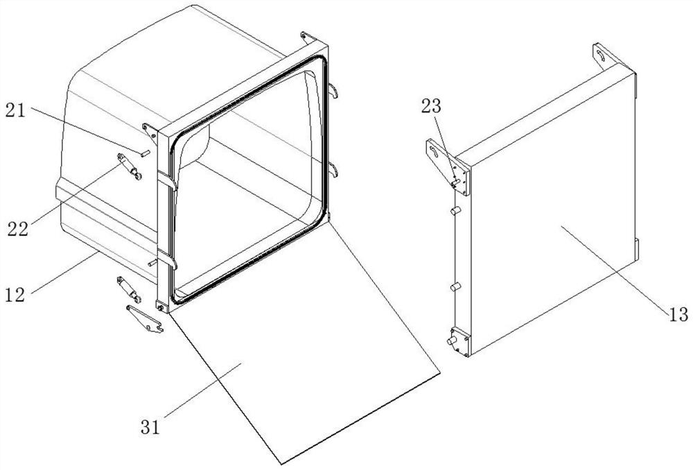
[0023]Please refer toimage 3 The telescopic mechanism 20 includes a No. 1 connecting rod 21 connected to the outer wall of the housing 12, a No. 2 electric push rod 22 is connected to the outer wall of the No. 1 connecting rod 21, a No. 2 connecting rod 23 is connected to the outer wall of the rear door 13, and a No. 2 electric push The output end of the rod 22 is connected with the No. 2 connecting rod 23 to facilitate the opening of the rear door 13.
[0024]Please refer toFigure 4 The sliding mechanism 30 includes a slide plate 31 connected to the bottom end of one side of the housing 12, the outer wall of the slide plate 31 is provided with a connecting block 32, the inside of the rear door 13 is provided with a rope groove 33, and the inside of the rear door 13 is located on one side of the rope groove 33 with The output end of the motor 34 is connected with a rotating shaft 35, and one end of the rotating shaft 35 is connected with a rope disc 36, so as to facilitate the displacement of the sliding plate 31.
[0025]Please refer toFigure 1-4, The No. 1 electric push rod 14, the No. 2 electric push rod 22 and the motor 34 are all electrically connected to an external power source through wires, so that the No. 1 electric push rod 14, the No. 2 electric push rod 22 and the motor 34 are energized and operated.
[0026]Please refer toFigure 4 A rope is connected to the outer wall of the rope reel 36, and one end of the rope passes through the rope groove 33 and is connected to the connecting block 32, which facilitates the displacement of the slide plate 31 by the rope.
[0027]Please refer toimage 3 withFigure 4 The sliding plate 31 and the housing 12 are connected by a rotating shaft to facilitate the relative rotation of the sliding plate 31 and the housing 12. The outer wall of the connecting block 32 fits with the inner wall of the rope groove 33, so that the outer wall of the connecting block 32 and the inner wall of the rope groove 33 fit together. The rear door 13 The outer wall is provided with a plurality of fixing posts, which fit with the outer wall of the lower door hook 15 and the fixing plate 16, which is convenient for fixing the rear door 13.
[0028]Working principle: First, start the No. 1 electric push rod 14. The operation of the No. 1 electric push rod 14 drives the lower door hook 15 to rotate. The lower door hook 15 rotates to separate the lower door hook 15 from the fixed post of the rear door 13, canceling the rear door 13 The second electric push rod 22 is activated, the second electric push rod 22 rotates relative to the first connecting rod 21 and the second connecting rod 23, driving the second connecting rod 23 to move, and the second connecting rod 23 displacement drives the rear door 13 is opened, and the motor 34 is started at the same time. The rotation of the motor 34 drives the shaft 35 to rotate. The rotation of the shaft 35 drives the rope reel 36 to rotate. The rope reel 36 rotates to make the rope extend from the rope groove 33, and the sliding plate 31 is lowered to contact the ground. The rubbish slides down the slide plate 31. After completion, the motor 34 is started. The motor 34 runs to drive the rope to shrink and drive the slide plate 31 to rotate. At the same time, the No. 2 electric push rod 22 is started to drive the rear door 13 to rotate, so that the rear door 13 and the shell 12 fit , The No. 1 electric push rod 14 is activated to drive the lower door hook 15 to rotate, and the lower door hook 15 and the fixed plate 16 are attached to the fixed post of the rear door 13, and the rear door 13 is closed.
[0029]For those skilled in the art, it is obvious that the present invention is not limited to the details of the foregoing exemplary embodiments, and the present invention can be implemented in other specific forms without departing from the spirit or basic characteristics of the present invention. Therefore, from any point of view, the embodiments should be regarded as exemplary and non-limiting. The scope of the present invention is defined by the appended claims rather than the foregoing description, and therefore it is intended to fall within the claims. All changes within the meaning and scope of equivalent elements of are included in the present invention. Any reference signs in the claims should not be regarded as limiting the claims involved.

PUM

no PUM

Description & Claims & Application Information

We can also present the details of the Description, Claims and Application information to help users get a comprehensive understanding of the technical details of the patent, such as background art, summary of invention, brief description of drawings, description of embodiments, and other original content. On the other hand, users can also determine the specific scope of protection of the technology through the list of claims; as well as understand the changes in the life cycle of the technology with the presentation of the patent timeline. Login to view more.
Why Eureka
Try Eureka