Plastic circular weaving machine supporting structure

A technology of supporting structure and circular loom, which is applied to circular looms, looms, textiles, etc., can solve the problems of unfavorable product promotion and sales, insufficient technical solutions, increased use costs, etc., and achieves convenient replacement and operation, and structural optimization. , Improve the effect of rotation

Pending Publication Date: 2021-02-02
PINGYANG DAYU PLASTIC MACHINERY
View PDF0 Cites 0 Cited by
  • Summary
  • Abstract
  • Description
  • Claims
  • Application Information

AI Technical Summary

Problems solved by technology

[0002] In the existing plastic circular loom, rollers or rollers are set between the upper door ring and the lower door ring to form a rolling track for the shuttle to run. The rollers or rollers are positioned axially and support the upper and lower door rings to ensure the distance between the upper and lower door rings. When the damaged rollers or rollers need to be replaced, the upper and lower door rings need to be enlarged. Only the distance between the door rings can remove the rotating shaft, and then the rollers and rollers can be replaced, especially when a small number of rollers or rollers need to be replaced, it is also necessary to disassemble all the rotating shafts from the upper door ring to lift the upper door ring, which is time-consuming It is laborious, resulting in a greatly increased cost of use, which is not conducive to product promotion and sales
[0003] In view of the above, the applicant has applied for a plastic circular loom to overcome the above-mentioned defects. Although this plastic circular loom can facilitate the replacement of the rollers and protect the rollers and meet the expected purpose, its technical solution is not perfect enough. , room for improvement

Method used


Image

  • Plastic circular weaving machine supporting structure
  • Plastic circular weaving machine supporting structure
  • Plastic circular weaving machine supporting structure

Examples


Embodiment Construction

[0034] In order to enable those skilled in the art to better understand the solutions of the present invention, the technical solutions in the embodiments of the present invention will be clearly and completely described below in conjunction with the drawings in the embodiments of the present invention. Obviously, the described embodiments are only It is an embodiment of a part of the present invention, but not all embodiments. Based on the embodiments of the present invention, all other embodiments obtained by persons of ordinary skill in the art without making creative efforts shall fall within the protection scope of the present invention.

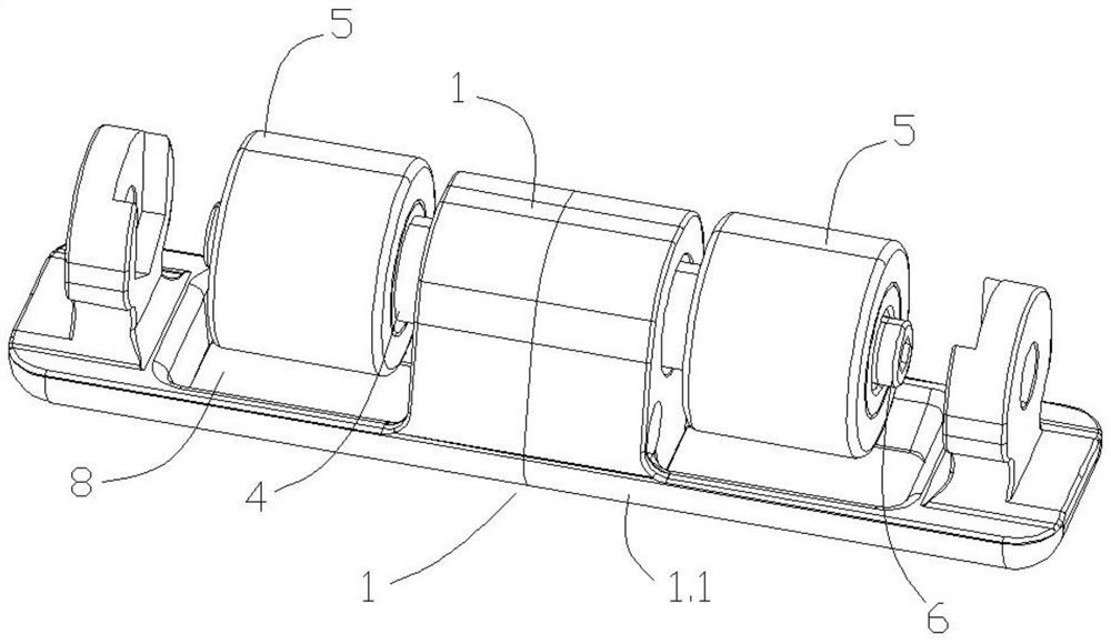
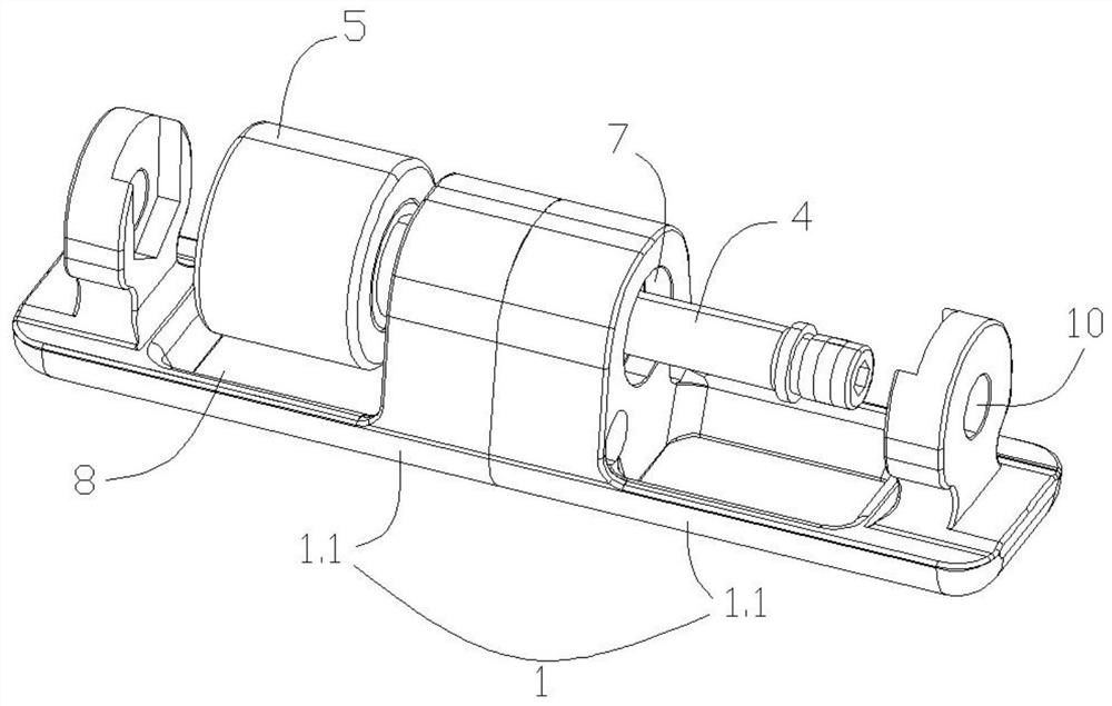
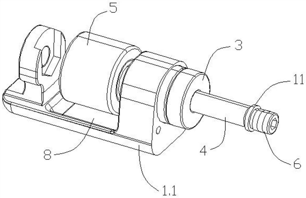
[0035] In the description of the present invention, it should be noted that the terms "center", "upper", "lower", "left", "right", "vertical", "horizontal", "inner", "outer" etc. The indicated orientation or positional relationship is based on the orientation or positional relationship shown in the drawings, and is only for the convenie...


PUM


Abstract

The invention discloses a plastic circular weaving machine supporting structure. The structure comprises a base, a bearing, a rotating shaft, a roller body and a locking piece, wherein the rotating shaft is rotatably and horizontally arranged in the base through the bearing, the rotating shaft comprises a supporting part and a rotating part which do not coincide with each other, the supporting part is rotatably arranged in a base shaft seat, and the roller body is fixedly connected with the rotating part into a whole through the locking piece. The roller body replaces a bearing type roller inthe prior art, the overall rotating effect is effectively improved, the problem that heat is directly transmitted to the roller body is overcome, and the structure has the technical effects of being optimized in structure and reliable in supporting.

Description

technical field [0001] The invention relates to the technical field of plastic weaving machines, in particular to a supporting structure of a plastic circular loom. Background technique [0002] In the existing plastic circular loom, rollers or rollers are set between the upper door ring and the lower door ring to form a rolling track for the shuttle to run. The rollers or rollers are positioned axially and support the upper and lower door rings to ensure the distance between the upper and lower door rings. When the damaged rollers or rollers need to be replaced, the upper and lower door rings need to be enlarged. Only the distance between the door rings can remove the rotating shaft, and then the rollers and rollers can be replaced, especially when a small number of rollers or rollers need to be replaced, it is also necessary to disassemble all the rotating shafts from the upper door ring to lift the upper door ring, which is time-consuming Laborious, resulting in greatly ...

Claims


Application Information

Patent Timeline
Patent Type & Authority Applications(China)
IPC IPC(8): D03D37/00
CPCD03D37/00
Inventor 陈达陈上利
Owner PINGYANG DAYU PLASTIC MACHINERY
Why Eureka
Try Eureka