

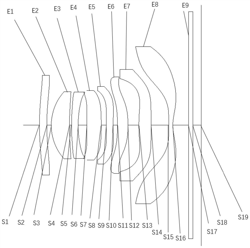
Optical imaging lens and electronic equipment
An optical imaging lens and imaging surface technology, which is applied in the field of optical imaging, can solve the problem that the optical imaging lens is difficult to take into account the shooting quality and the structure is light and thin, and achieves the effect of good imaging effect and excellent lightness and thinness.
- Summary
- Abstract
- Description
- Claims
- Application Information
AI Technical Summary
Problems solved by technology
Method used
Image

Examples
Embodiment Construction
[0019] The following will clearly and completely describe the technical solutions in the embodiments of the present application with reference to the drawings in the embodiments of the present application. Obviously, the described embodiments are part of the embodiments of the present application, not all of them. Based on the embodiments in this application, all other embodiments obtained by persons of ordinary skill in the art without making creative efforts belong to the scope of protection of this application.
[0020] The terms "first", "second" and the like in the specification and claims of the present application are used to distinguish similar objects, and are not used to describe a specific sequence or sequence. It should be understood that the terms so used are interchangeable under appropriate circumstances such that the embodiments of the application can be practiced in sequences other than those illustrated or described herein, and that references to "first," "sec...
PUM
 Abstract
Description
Claims
Application Information