
Outdoor low-voltage power distribution cabinet

A power distribution cabinet and low-voltage technology, which is applied in the field of outdoor low-voltage power distribution cabinets, can solve the problems of time-consuming and labor-intensive, large floor space, etc., and achieve the effect of improving safety and improving work efficiency

Inactive Publication Date: 2021-02-02
余苏祥
View PDF0 Cites 2 Cited by
  • Summary
  • Abstract
  • Description
  • Claims
  • Application Information

AI Technical Summary

Problems solved by technology

[0002] The low-voltage power distribution cabinet is a basic power distribution device that integrates residual current action protectors and air circuit breakers in a reasonable combination to achieve centralized power supply control and protection functions such as grounding, overload, and short circuit. Outdoor power distribution cabinets During use, a waterproof ceiling is required to reduce the infiltration of rainwater into the power distribution cabinet. However, most of the existing waterproof ceilings are fixed, which block the sunlight while waterproofing, but the fixed type has a large footprint. Problem, in addition, the manual control of the drawer components of the existing power distribution cabinet is time-consuming and laborious, and there is a certain degree of safety

Method used


Image

  • Outdoor low-voltage power distribution cabinet
  • Outdoor low-voltage power distribution cabinet
  • Outdoor low-voltage power distribution cabinet

Examples


Embodiment Construction

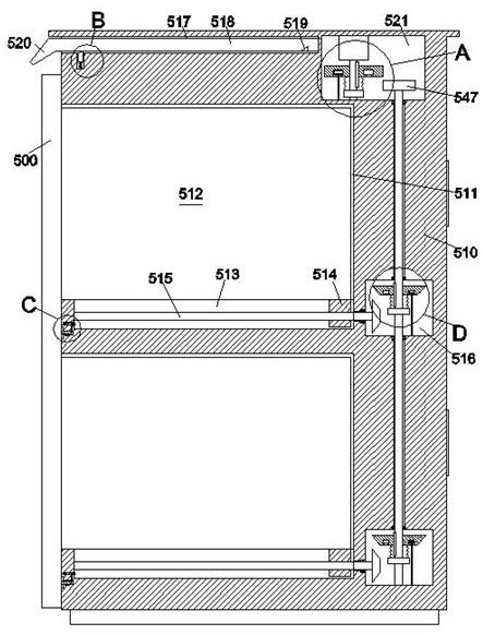
[0017] Combine below Figure 1-5 The present invention is described in detail, and for convenience of description, the orientations mentioned below are now stipulated as follows: figure 1 The up, down, left, right, front and back directions of the projection relationship itself are the same.

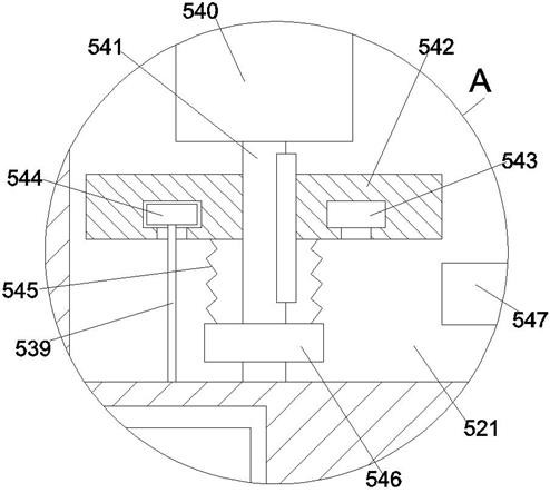
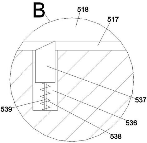
[0018] refer to Figure 1-5 , an outdoor low-voltage power distribution cabinet according to an embodiment of the present invention, comprising a main cabinet body 510, inside the main cabinet body 510 there is a storage room 511 that is vertically symmetrical and opens to the left, and inside the storage room 511 There is a chest of drawers 512, which is characterized in that: the upper side of the storage room 511 on the upper side is provided with a rain shield mechanism, and the right side of the weather shield mechanism is provided with a drive control room 521, and the drive control room 521 is equipped with There is a drive and control mechanism, the bottom wall of the storage r...


PUM


Abstract

The invention discloses an outdoor low-voltage power distribution cabinet which comprises a main cabinet body. Storage chambers which are vertically symmetrical and are provided with leftward openingsare formed in the main cabinet body, drawer cabinets are arranged in the storage chambers, a rain baffle mechanism is arranged on the upper side of the storage chamber on the upper side, a drive control chamber is arranged on the right side of the rain baffle mechanism, and a drive control mechanism is arranged in the drive control chamber; a guide-in groove is formed in the bottom wall of each storage chamber in a connection mode, a guide-in block fixedly connected with the drawer cabinet is connected into the guide-in groove in a sliding fit mode, a guide-in screw rod extending leftwards and rightwards is connected into the guide-in block in a threaded fit mode, and a joint control chamber is arranged on the right side of the guide-in groove; and a joint control mechanism used for beingconnected with the drive control mechanism in a power fit mode is arranged in the joint control chamber, and a self-breaking linkage mechanism used for controlling the joint control mechanism is arranged on the left side of the guide groove. Safety during maintenance and the working efficiency of maintenance are improved.

Description

technical field [0001] The invention relates to the technical field of power distribution cabinets, in particular to an outdoor low-voltage power distribution cabinet. Background technique [0002] The low-voltage power distribution cabinet is a basic power distribution device that integrates residual current action protectors and air circuit breakers in a reasonable combination to achieve centralized power supply control and protection functions such as grounding, overload, and short circuit. Outdoor power distribution cabinets In the process of use, it is necessary to match the waterproof ceiling to reduce the infiltration of rainwater into the interior of the power distribution cabinet. However, the existing waterproof ceiling is mostly fixed, which also blocks the sunlight while waterproofing, but the fixed type has a large footprint. Problem, in addition, the manual control of the drawer components of the existing power distribution cabinet is time-consuming and laborio...

Claims


Application Information

Patent Timeline
Patent Type & Authority Applications(China)
IPC IPC(8): H02B1/30H02B1/28H02B11/127
CPCH02B1/28H02B1/30H02B11/127
Inventor 余苏祥
Owner 余苏祥
Learn More