Camera module and mobile terminal
A camera module and mobile terminal technology, applied in the camera field, can solve problems such as enlarged aperture diameter, enlarged lens, and broken filter, so as to avoid the effect of image quality
- Summary
- Abstract
- Description
- Claims
- Application Information
AI Technical Summary
Problems solved by technology
Method used
Image
Examples
no. 1 example
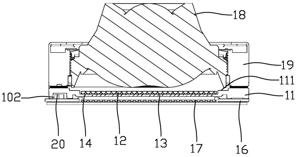
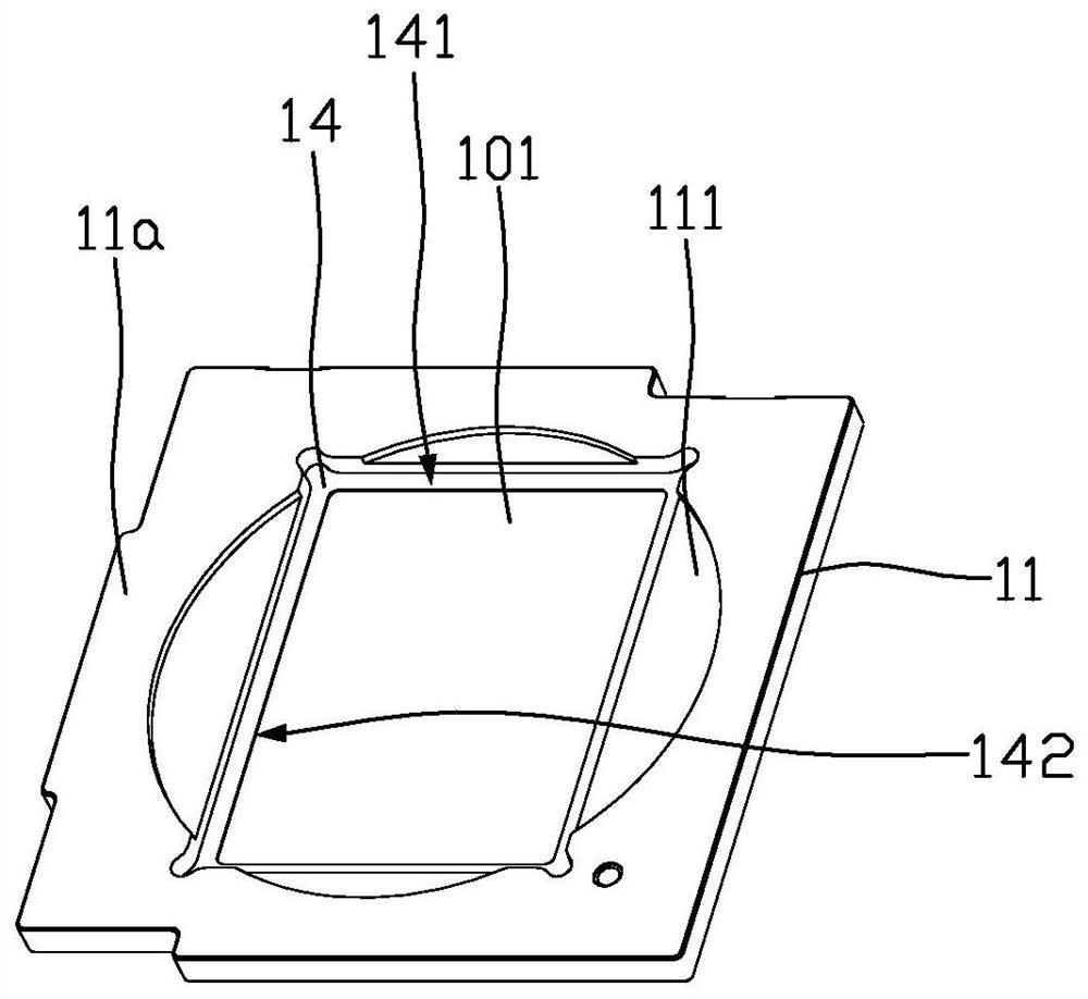
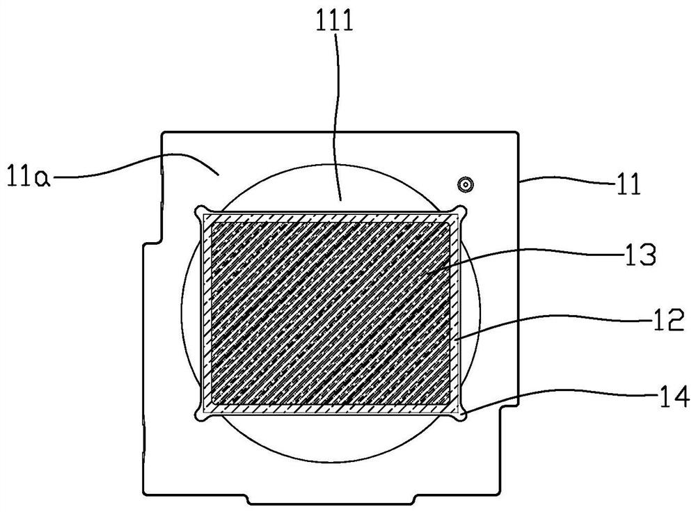
[0026] figure 1 is a schematic cross-sectional structure diagram of the camera module according to the first embodiment of the present invention, figure 2 It is a schematic diagram of the three-dimensional structure of the support base of the first embodiment of the present invention, image 3 It is a top view structure schematic diagram when a transparent support portion and a filter are set on the support base of the first embodiment of the present invention, Figure 4 It is a schematic cross-sectional structural view of the assembly of the support seat, the transparent support portion and the filter according to the first embodiment of the present invention, Figure 5 Yes Figure 4 The partial enlarged structural diagram of the supporting base, transparent supporting part and optical filter shown, please refer to Figure 1 to Figure 5 , the camera module includes a support base 11 and an optical filter 12, the support base 11 is provided with a light-through hole 101, t...
no. 2 example
[0042] Image 6 It is a schematic cross-sectional structural view of the assembly of the support seat, the transparent support portion and the filter according to the second embodiment of the present invention, Figure 7 Yes Image 6 The schematic diagram of the local enlarged structure of the supporting seat and the filter shown, as shown in Image 6 and Figure 7 As shown, the camera module of this embodiment is substantially the same as the camera module of the first embodiment, the difference lies in the way the transparent support portion 13 is connected to the carrying platform 14 .
[0043] Furthermore, the carrying platform 14 is provided with a second inner surface 143 , and the second inner surface 143 is provided with an installation groove 103 , and the transparent support part 13 is installed in the installation groove 103 . In this embodiment, the second inner surface 143 extends along the axis of the light through hole 101 , the installation groove 103 is arran...
no. 3 example
[0046] Figure 8 It is a schematic cross-sectional structural view of the assembly of the support seat, the transparent support part and the optical filter according to the third embodiment of the present invention, Figure 9 Yes Figure 8 The schematic diagram of the local enlarged structure of the support seat, transparent support part and filter shown, as shown in Figure 8 and Figure 9 As shown, the camera module of this embodiment is substantially the same as the camera module of the first embodiment, the difference lies in the way the transparent support portion 13 is connected to the carrying platform 14 .
[0047] Specifically, the carrying platform 14 is provided with a carrying surface 144 , the transparent supporting portion 13 is connected to the carrying surface 144 , the side of the carrying surface 144 close to the axis of the light hole 101 is recessed to form a carrying step 145 , and the transparent supporting portion 13 is connected to the carrying step 1...
PUM
| Property | Measurement | Unit |
|---|---|---|
| Thickness | aaaaa | aaaaa |
Abstract
Description
Claims
Application Information
 - R&D
- Intellectual Property
- Life Sciences
- Materials
- Tech Scout
- Unparalleled Data Quality
- Higher Quality Content
- 60% Fewer Hallucinations
Browse by: Latest US Patents, China's latest patents, Technical Efficacy Thesaurus, Application Domain, Technology Topic, Popular Technical Reports.
© 2025 PatSnap. All rights reserved.Legal|Privacy policy|Modern Slavery Act Transparency Statement|Sitemap|About US| Contact US: help@patsnap.com


