Multi-head laser printing equipment for shoes

A laser printing and multi-head technology, which is applied in laser welding equipment, welding equipment, metal processing equipment, etc., can solve the problems of occupying production materials, high scrap rate, graphic misalignment, etc., to meet production needs, good printing effect and low production cost low effect

Pending Publication Date: 2021-02-05
晋江市无极激光工艺品工贸有限公司
View PDF0 Cites 0 Cited by
  • Summary
  • Abstract
  • Description
  • Claims
  • Application Information

AI Technical Summary

Problems solved by technology

There are also differences in the printing effect of the same laser emitter on different printing materials, and the existing laser laser printer usually only has one laser emitter. Therefore, when the same pattern on the shoe is laser printed When using different laser printing equipment, it may be necessary to use different laser printing equipment, and the processing on different equipment on the shoes needs to be re-clamped, and the processing benchmark may deviate, which will lead to partial misalignment of the graphics on the shoes, and the scrap rate is relatively high. The turnover of different equipment needs to occupy a certain amount of production materials, which increases production costs

Method used


Image

  • Multi-head laser printing equipment for shoes
  • Multi-head laser printing equipment for shoes
  • Multi-head laser printing equipment for shoes

Examples


Embodiment 1

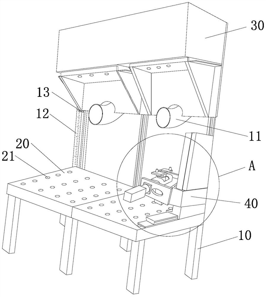
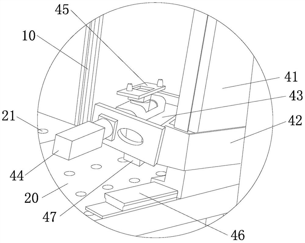
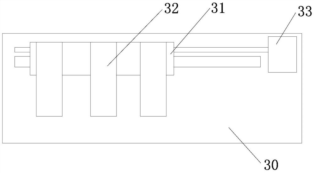
[0035] Such as Figure 1-Figure 3 As shown, the present embodiment provides a multi-head laser printing device for shoes, including a frame 10, a workbench 20 arranged horizontally on the frame 10, vertically slidably connected to the frame 10 and positioned on the front of the workbench 20. The laser main box 30 on the top and the laser motor (not shown) for driving the laser main box 30 to slide, wherein, the specific transmission connection structure between the laser motor and the laser main box 30 is a conventional structure, such as a screw mandrel Assemblies, rack and pinion assemblies or worm gear assemblies, etc., will not be described in detail here. Preferably, the frame 10 is fixedly connected with a vertically arranged scale 12, and the laser main box 30 is provided with an indicator arrow 13 cooperating with the scale 12, which is convenient for the operator to understand and adjust the laser main box 30 on the frame 10. height position.

[0036] The inner cavi...

Embodiment 2

[0042] Such as Figure 4 shown, and refer to Figure 1-Figure 3 , this embodiment provides a laser printing all-in-one machine, which is further improved on the basis of the multi-head laser printing equipment for shoes provided in Embodiment 1, that is, what this embodiment provides is essentially a multi-head laser printing equipment for shoes equipment.

[0043] Specifically, the laser printing all-in-one machine or shoe multi-head laser printing equipment provided in this embodiment also includes a main box 50 vertically slidably connected to the frame 10 and positioned directly above the workbench 20 and a main box 50 for driving The sliding inkjet motor (not shown in the figure), that is, the laser inkjet printer provided in this embodiment or the multi-head laser printing equipment for shoes includes a laser main body that is vertically slidably connected to the frame 10 and is positioned directly above the workbench 20. Box 30 and spray painting main box 50. Wherein...


PUM


Abstract

The invention provides multi-head laser printing equipment for shoes. The equipment comprises a rack, a workbench arranged on the rack, a laser main box vertically connected to the rack in a sliding mode and located over the workbench, and a laser motor used for driving the laser main box to slide. A sliding frame is horizontally connected to an inner cavity of the laser main box in a sliding mode, a plurality of laser emitters which are sequentially arranged at equal intervals in the sliding direction of the sliding frame are arranged on the sliding frame, the types of the laser emitters aredifferent from one another, and penetrating holes are formed in the positions, corresponding to the laser emitters, of the lower end of the laser main box. The plurality of different types of laser emitters are connected into the laser main box in a sliding mode so that the same equipment can achieve laser printing of different types without clamping the shoes again, the diversified production requirements of the shoes are met, the rejection rate is relatively low, and meanwhile, due to the fact that material turnover does not exist between laser machining and inkjet machining, the productioncost is relatively low.

Description

technical field [0001] The invention relates to a shoe production device, in particular to a multi-head laser printing device for shoes. Background technique [0002] The graphics on traditional shoes are usually made by embossing on the leather. In order to surpass the boundary between the upper and the sole and improve the layout space of the graphics on the shoes, laser laser and inkjet printing are used. It is more and more used in the production of shoe upper patterns. Among them, for laser laser printing to make shoe upper patterns, the printing effect formed by different laser emitters on the same printing material is not the same. There are also differences in the printing effect of the same laser emitter on different printing materials, and the existing laser laser printer usually only has one laser emitter. Therefore, when the same pattern on the shoe is laser printed When using different laser printing equipment, it may be necessary to use different laser printin...

Claims


Application Information

Patent Timeline
Patent Type & Authority Applications(China)
IPC IPC(8): B23K26/362B23K26/402B23K26/70
CPCB23K26/362B23K26/402B23K26/702
Inventor 王云炳
Owner 晋江市无极激光工艺品工贸有限公司
Why Eureka
Try Eureka