
A compounding structure and injection molding equipment with the structure

An injection molding equipment and compounding technology, which are applied in the field of compounding structure and injection molding equipment with the structure, can solve the problems of reduced strength of finished products, easily damaged carbon fiber material strength, low production efficiency, etc., so as to avoid cost increase, The effect of reducing shear and heating time

Active Publication Date: 2018-12-28
NINGBO SHUANGMA MASCH IND CO LTD
View PDF5 Cites 0 Cited by
  • Summary
  • Abstract
  • Description
  • Claims
  • Application Information

AI Technical Summary

Problems solved by technology

However, there are currently four mature application forms of carbon fiber. One is the hand lay-up method, in which the carbon fiber sheets impregnated with glue are cut into layers, or resin is applied while layering, and then hot-pressed. , the strength of the carbon fiber product made by this method is high, but the production efficiency is low; one is the winding molding method, which winds the carbon fiber monofilament on the carbon fiber shaft, this method is only suitable for making cylinders and hollow vessels, and the production efficiency Low; one is the molding method, which is to put the pre-impregnated carbon fiber material into the metal mold, pressurize the excess glue to overflow, and then cure it at high temperature. The carbon fiber products made by this method The strength is high, but the production efficiency is also low, and structural parts cannot be made; one is the long-fiber pellet injection molding method, which pre-processes carbon fibers to make pellets, and then injection molding through an injection molding machine. Although this method solves the problem of production efficiency However, for the carbon fiber with long fiber length in the pellets, under the shearing and heating action of the screw of the injection molding machine and the hot runner, only 30% of the finished product has a fiber length of more than 5mm, resulting in a large strength of the finished product. reduce
[0003] Since the strength of carbon fiber material itself is easily damaged at high temperature, and the length of carbon fiber and its interlacing complexity in the finished product will affect the strength of its finished product, it can be seen that the current application of carbon fiber will soon be guaranteed The strength of carbon fiber material and the production process of mass industrial production are vacant, and the equipment for continuous production and molding processing of carbon fiber is also in a blank state in the market. Therefore, it is necessary to develop a method that can reduce the time of carbon fiber damage by high temperature and Equipment that can increase the length of carbon fibers in finished products and meet the efficiency requirements of industrial mass production is particularly necessary
[0004] Moreover, in the prior art, most of the compounding structures of injection molding machines are equipped with a feed inlet, which cannot meet the needs of different heating times and different heating temperatures for the materials to be processed under different processes, and has little applicability to working conditions

Method used


Image

  • A compounding structure and injection molding equipment with the structure
  • A compounding structure and injection molding equipment with the structure
  • A compounding structure and injection molding equipment with the structure

Examples


Embodiment 1

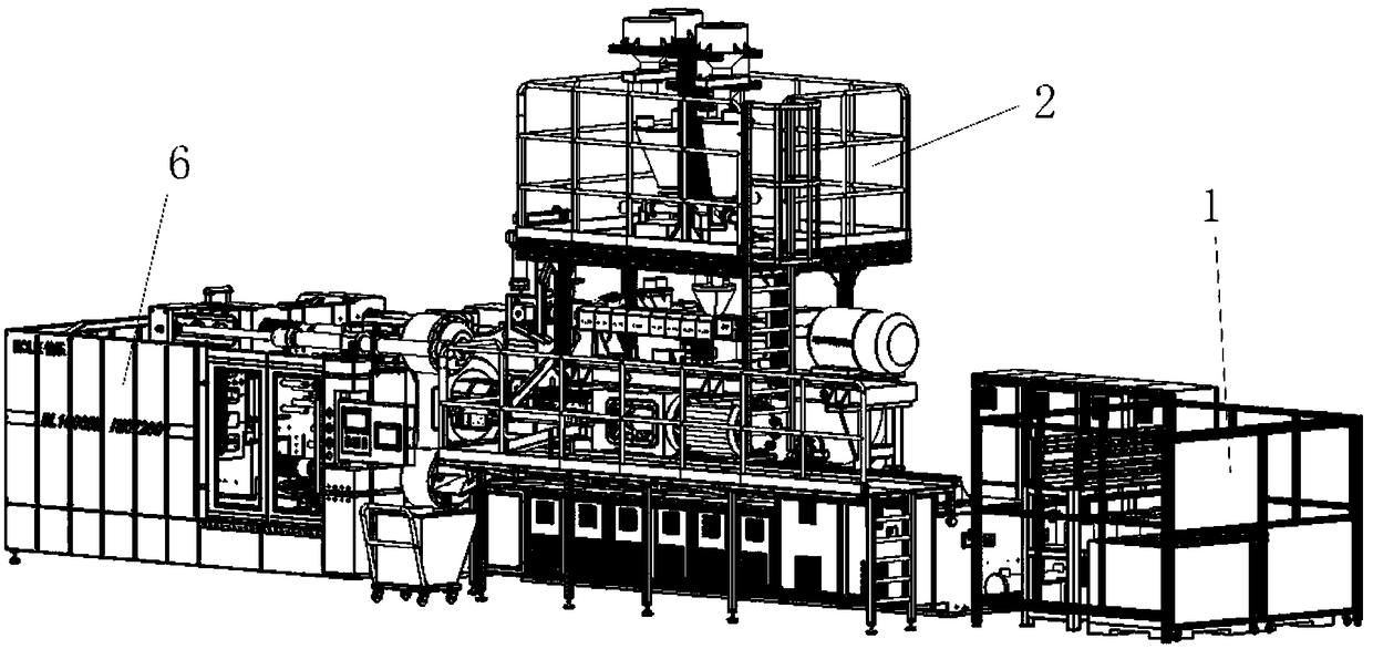
[0037] Like the carbon fiber forming equipment described above, the difference in this embodiment is that the fiber feeding structure 1 is used to store the continuous fibers, and transport the continuous fibers to the feeding control structure through a hose middle.

Embodiment 2

[0039] Like the carbon fiber molding equipment described above, the difference in this embodiment is that the plastic feeding structure 2 includes a feeding scale, the feeding scale is used to measure the formula material, and the plastic feeding structure 2 The structure is provided with at least one feeding scale, each of which is used to weigh a formula material, and the plastic feeding structure sends the formula material into the feeding control structure through the bottom material opening . The feeding scale is equipped with a corresponding replenishing bin and a feeding device for realizing the functions of feeding and feeding, which facilitates continuous production, and the shape of the formula material includes granular.

Embodiment 3

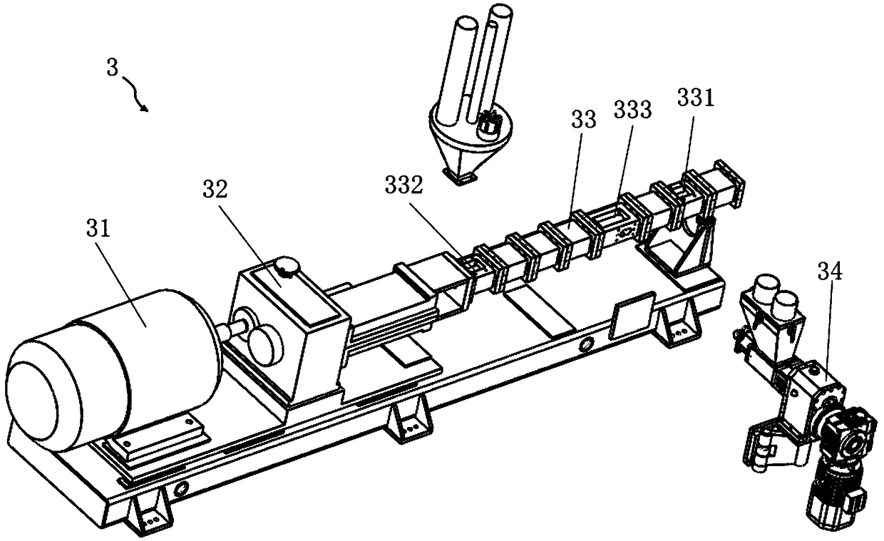
[0041] As the above-mentioned carbon fiber forming equipment, the present embodiment is different from it in that, as figure 2 As shown, the compounding structure 3 is used to shear and melt the material to be processed; the compounding structure 3 includes: a motor 31, a reducer 32, a screw assembly, and a screw barrel 33;

[0042]The motor 31 is used to provide power for the compounding process, the output shaft of the motor 31 is connected to the input end of the reducer 32, and the output end of the reducer 32 is connected to the fixed end of the screw assembly, The reducer 32 is used to drive the screw assembly to rotate around the axis; the screw assembly is composed of at least two screws arranged side by side, and at least one helix is ​​provided on the screw, when the material to be processed When moving along the advancing direction of the helix, various forms of helixes are provided, and the combination of various forms of helixes is more conducive to the shearing ...


PUM


Abstract

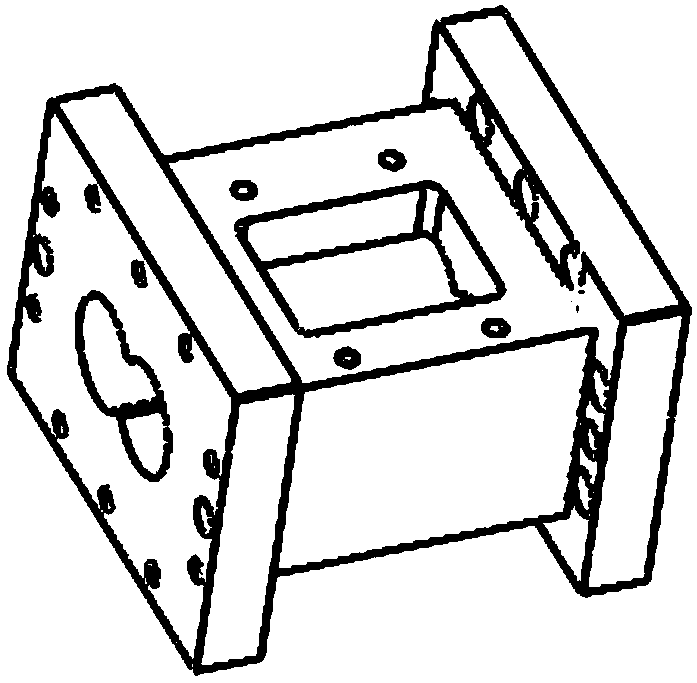
The invention discloses a mixing structure. The mixing structure comprises a mixing structure body which is used for shearing and melting to-be-machined materials. The mixing structure body comprises a screw cylinder which is used for providing implementation space for the mixing process. The mixing structure is characterized in that the screw cylinder comprises at least one cylinder assembly which is used for forming the screw cylinder; and each cylinder assembly comprises an opened cylinder and a closed cylinder, a through hole is formed in the opened cylinder, the to-be-machined materials are thrown into the mixing structure through the through hole, the closed cylinder is used for forming the screw cylinder, and a screw is arranged in the screw cylinder. Due to the cooperative installation of the opened cylinders and the closed cylinders, the positions of the through holes are changed, the length of the cylinders is changed, and therefore the condition that the requirements for the feeding position are different during practical production is met, the arrangement manners of the cylinders are more diversified, and various requirements for technological production are met.

Description

technical field [0001] The invention relates to the field of injection molding machines, in particular to a compounding structure and injection molding equipment with the structure. Background technique [0002] Carbon fiber is a new type of inorganic fiber material with a carbon content above 90% (mass fraction), with high specific strength, high specific modulus, high temperature resistance, corrosion resistance, fatigue resistance, radiation resistance, electrical conductivity, heat transfer, and relative density A series of excellent properties, such as small, are typical high-performance fibers. Carbon fiber not only has the inherent characteristics of carbon materials, but also has the softness and processability of textile fibers. The components made of carbon fibers are light in weight, high in specific stiffness, and have a wide range of applications. However, there are currently four mature application forms of carbon fiber. One is the hand lay-up method, in which...

Claims


Application Information

Patent Timeline
Patent Type & Authority Patents(China)
IPC IPC(8): B29C45/46B29C45/47B29C45/58B29C45/62B29C45/18
CPCB29C45/1808B29C45/1866B29C45/461B29C45/462B29C45/47B29C45/58B29C45/62B29C2045/466
Inventor 张洪施海明陈炽辉沈明聪邹骞
Owner NINGBO SHUANGMA MASCH IND CO LTD
Learn More