
Drawing-in gripper, drawing-in machine including such a gripper and process for drawing-in warp yarns on such a drawing-in machine

A technology of threading machine and shuttle clamp, applied in the field of warp threading machine and shuttle clamp, which can solve the problems of complex shuttle clamp manufacturing, tearing, yarn breakage, etc., and achieve simple geometric shape, low cost and simple shuttle clamp Effect

Pending Publication Date: 2021-02-05
STAUBLI SARGANS AG
View PDF8 Cites 0 Cited by
  • Summary
  • Abstract
  • Description
  • Claims
  • Application Information

AI Technical Summary

Problems solved by technology

The manufacture of this shuttle clamp is rather complex and requires specific control of its moving parts
The clip may not work with thicker or corespun fancy yarns and the hook may tear thicker or corespun fancy yarns
Furthermore, the shuttle clamp must be opened during the retraction movement in order to release the yarn at the end of the drawing-in cycle, which can lead to synchronization problems and machine downtime
In addition, the closing of the movable parts can cause the yarn to be pinched, the yarn fibers to become clogged, or in the worst case cause the yarn to break

Method used


Image

  • Drawing-in gripper, drawing-in machine including such a gripper and process for drawing-in warp yarns on such a drawing-in machine
  • Drawing-in gripper, drawing-in machine including such a gripper and process for drawing-in warp yarns on such a drawing-in machine
  • Drawing-in gripper, drawing-in machine including such a gripper and process for drawing-in warp yarns on such a drawing-in machine

Examples


Embodiment Construction

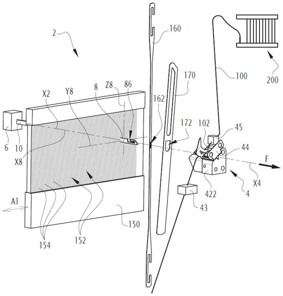
[0050] The drawing-in machine 2 partially shown in the figures comprises a yarn unit 4 for the positioning of a portion 102 of a yarn 100 intercepted from a warp 200, which for the sake of simplicity is only shown in figure 1 and Figure 4 Schematically represented on a smaller scale.

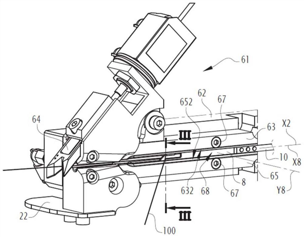
[0051] The drawing-in machine 2 also includes a drawing-in station 6, which figure 1 is shown schematically with a cube on the figure 2 and image 3 is shown on a larger scale and in a more realistic manner.

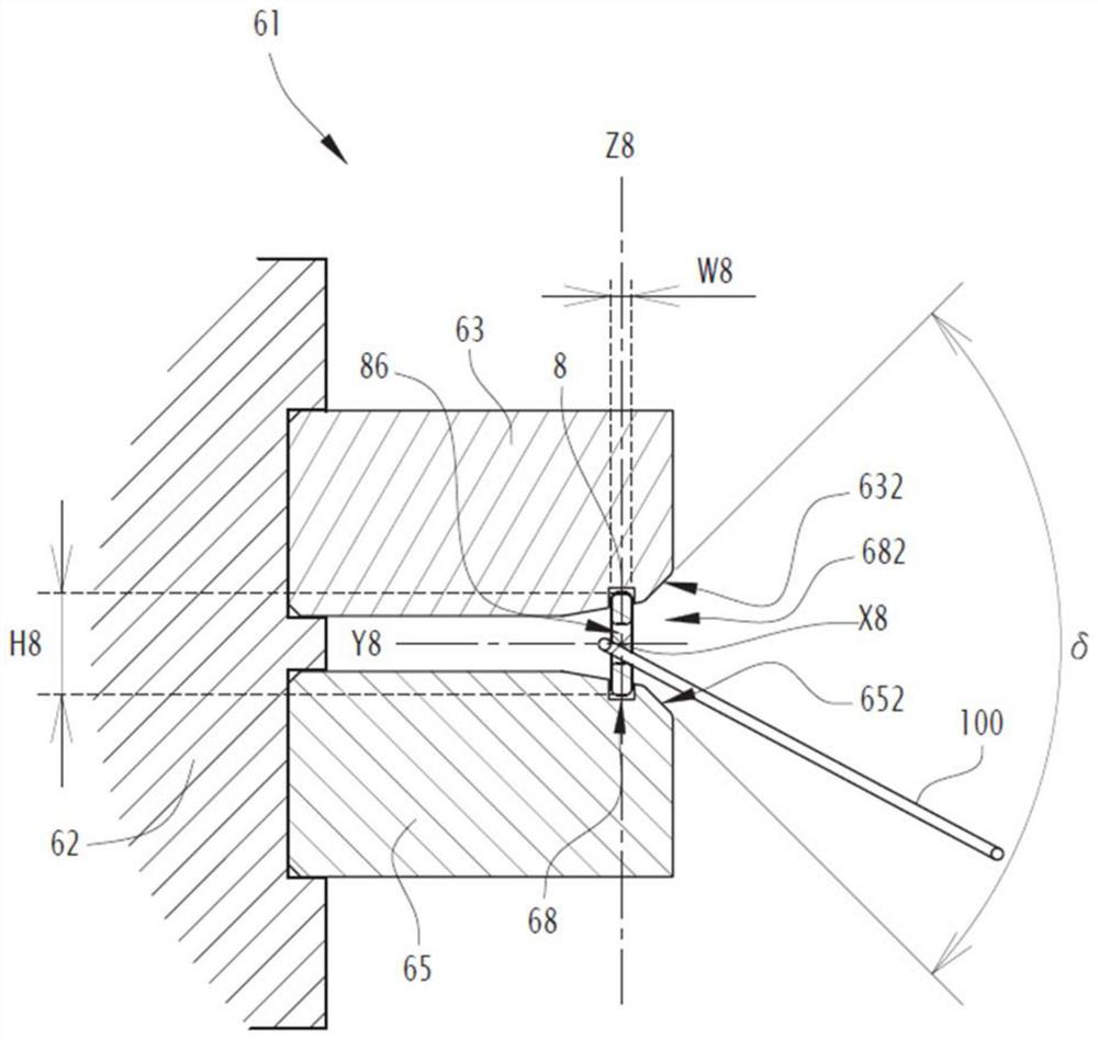
[0052] The threading machine 2 also comprises a shuttle clip 8 coupled to a belt 10 driven by the threading station 6 so that the threading machine 8 is positioned along the axis X2 of the threading machine. Figure 9 shown in the first or extended position and figure 2 The movement between the shown second position, in which, in the first or extended position, the shuttle clamp 8 cooperates with parts of the yarn unit 4, and in the second position, the shuttle clamp 8 is located i...


PUM


Abstract

A drawing-in gripper (8) for drawing warp yarns of extends longitudinally along a main axis (X8) between a gripper nose (82) and a coupling rear end (84). The gripper defines a yarn-receiving cavity (86) which extends, between the gripper nose and the coupling read end, through the gripper along a transverse axis perpendicular to the main axis. The gripper forms a bite portion (88), which extendslongitudinally at the rear of the gripper nose, and an entry opening (866) of the yarn-receiving cavity (86) is defined between a rear tip (882) of the bite portion and a rectilinear back surface (868) of the yarn receiving cavity. In a longitudinal plane (X8, Z8) perpendicular to the transverse axis (Y8), the yarn-receiving cavity (86) is L-shaped. An angle (beta), defined between the main axis (X8) and the rectilinear back surface (868) and measured in the longitudinal plane and within the yarn-receiving cavity (86), is between 90 degrees and 105 degrees, preferably equal to 90 degrees.

Description

technical field [0001] The present invention relates to a drawing-ingripper for threading warp yarns into various parts of the harness. The invention also relates to a drawing-in machine for threading warp threads, and a method for threading warp threads onto such a machine. [0002] The technical field of the invention is that of weaving preparation, in which a set of warp yarns (usually several thousand) must be threaded into several weaving implement elements, such as heddles, drop wires, reeds, in order for the loom to carry out the weaving operation . The warp threads must be introduced into the harness knitting elements and arranged parallel to each other in a specific order with respect to the healds (their vertical vibration will determine the movement of the bobbin in the loom). Background technique [0003] In the field of weaving preparation, automatic machinery is commonly used to fill the warp thread threaded from the warp beam into the continuous heddle of th...

Claims


Application Information

Patent Timeline
IPC IPC(8): D03J1/14
CPCD03J1/14
Inventor H·罗曼尼亚I·弗罗梅尔特
Owner STAUBLI SARGANS AG
Learn More