Installation method of high-pressure detachable cover plate type heat exchanger tube box

A technology of heat exchanger tube and installation method, applied in the direction of heat exchanger type, heat exchanger shell, indirect heat exchanger, etc., to achieve the effect of avoiding single-sided force and uniform force

Pending Publication Date: 2021-02-05
LONGHUA TECHNOLOGY GROUP (LUOYANG) CO LTD
View PDF0 Cites 0 Cited by
  • Summary
  • Abstract
  • Description
  • Claims
  • Application Information

AI Technical Summary

Problems solved by technology

[0004] The purpose of the present invention is to overcome the deficiencies in the prior art and provide a method for installing the tube box of a high-pressure detachable cover plate heat exchanger, which can ensure that the gasket is evenly stressed in the sealing surface under high-pressure conditions. Avoid the problem of excessive local deformation due to one-sided force on the sealing surface, achieve the purpose of effective sealing, and achieve the purpose of long-term safe operation under high-pressure conditions

Method used


Image

  • Installation method of high-pressure detachable cover plate type heat exchanger tube box
  • Installation method of high-pressure detachable cover plate type heat exchanger tube box
  • Installation method of high-pressure detachable cover plate type heat exchanger tube box

Examples


Embodiment 1

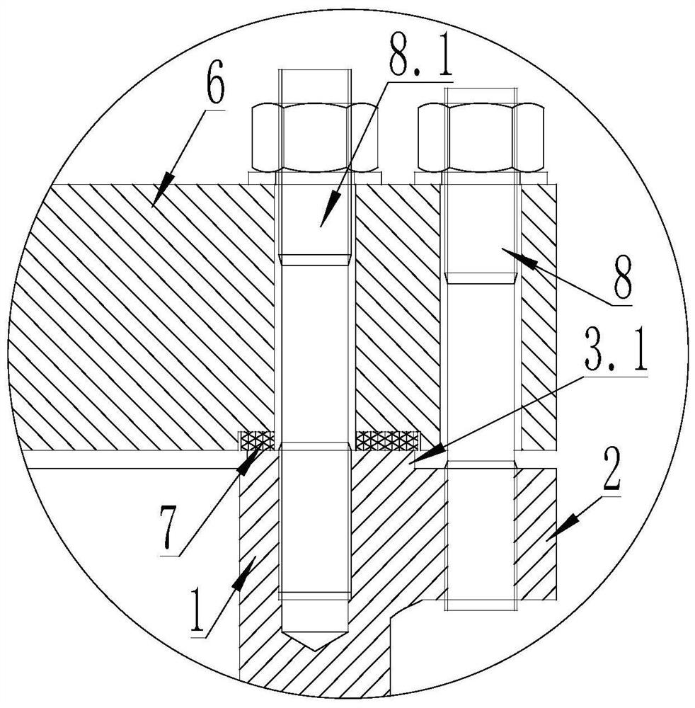
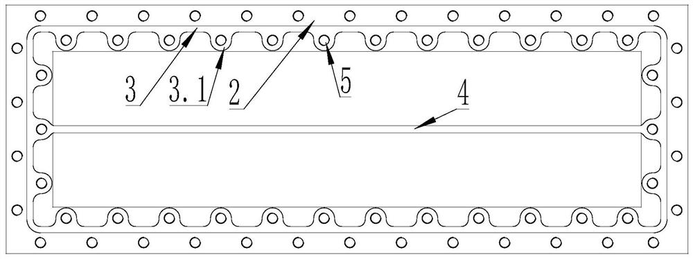
[0017] The middle part of the pipe box 1 is provided with an intermediate partition 4, the upper end of the pipe box 1 is provided with a flange 2, and the upper surface of the pipe box 1 is provided with a rectangular boss sealing surface 3, and the inner side of the rectangular boss sealing surface 3 is evenly distributed with ear-shaped boss sealing surfaces 3.1 , the rectangular boss sealing surface 3 is integrally formed with the ear-shaped boss sealing surface to form the boss sealing surface, the inner screw hole 5 is set in the middle of the ear-shaped boss sealing surface 3.1, the upper end of the pipe box 1 is provided with a cover plate 6, and the cover plate 6 is close to the surroundings The outer screw holes 11 are evenly distributed on the edge, the lower surface of the cover plate 6 is provided with a rectangular groove sealing surface 9, the inner side of the rectangular groove sealing surface 9 is provided with an ear-shaped groove sealing surface 10, and the m...

Embodiment 2

[0019] Sealing pads 7 are evenly distributed between the groove sealing surface and the boss sealing surface.

Embodiment 3

[0021] Place the gasket 7 in the sealing surface of the groove, install the outer bolt 8 on the outer screw hole 11 of the cover plate 6 and the screw hole on the flange 2, and install the outer bolt 8 on the inner screw hole 5 on the cover plate 6 and the inner screw hole on the pipe box 1 The screw hole 5 corresponds to the installation of the inner bolt 8.1. The cover plate 6 is connected with the pipe box 1 through the outer bolt 8 and the inner bolt 8.1. The gasket 7 is pressed tightly, and the outer bolt 8 and the inner bolt 8.1 are located between two adjacent gaskets 7, which can ensure that the gasket 7 is evenly stressed and deformed uniformly, and can avoid single-sided force and local deformation of the gasket 7 If the problem is too large, the purpose of effective sealing is achieved. Under high-pressure conditions, the outer bolt 8 and the inner bolt 8.1 are stressed at the same time to ensure that the gasket 7 is evenly stressed in the sealing surface and realize...


PUM


Abstract

An installation method of a high-pressure detachable cover plate type heat exchanger tube box comprises the following steps that a middle partition plate is arranged in the middle in the tube box, a flange is arranged at the upper end of the tube box, a rectangular boss sealing face is arranged on the upper surface of the tube box, lug-shaped boss sealing faces are evenly distributed on the rectangular boss sealing face, inner side screw holes are formed in the middles of the lug-shaped boss sealing faces, and a cover plate is arranged at the upper end of the tube box; outer side screw holes are evenly distributed in the positions, close to the peripheral edge, of the cover plate, a rectangular groove sealing face is arranged on the lower surface of the cover plate, an ear-shaped groove sealing face is arranged at the inner side of the rectangular groove sealing face, inner side screw holes are formed in the middle of the ear-shaped groove sealing face, and outer side bolts are arranged on the outer side screw holes of the cover plate and correspond to the screw holes in the flange; and the inner side screw holes in the cover plate and the inner side screw holes in the tube box arecorrespondingly provided with inner side bolts; Under the high-pressure working condition, it can be guaranteed that a sealing gasket is evenly stressed in the sealing face, the problem that local deformation is too large due to the fact that the single face of the sealing face is stressed is solved, the purpose of effective sealing is achieved, and the purpose of long-term safe operation under the high-pressure working condition is achieved.

Description

technical field [0001] The invention relates to the technical field of industrial heat exchangers, in particular to a method for installing a tube box of a high-pressure detachable cover plate heat exchanger. Background technique [0002] In the field of industrial heat exchanger technology, for the medium with high thermal resistance of dirt or the working conditions where the dirt cannot be removed by chemical methods, it is advisable to adopt a tube and box structure that can be cleaned mechanically, such as a detachable cover plate heat exchanger. The original design of the sealing surface of the detachable cover plate heat exchanger adopts a narrow tenon-groove sealing structure. Under high pressure conditions, the sealing surface of the detachable cover plate heat exchanger is subjected to single-sided force, and the force on the sealing surface is not strong. Uniformity can easily lead to leakage of the sealing surface of the pipe box, thereby causing potential safety...

Claims


Application Information

Patent Timeline
IPC IPC(8): F28D9/00F28F9/02F28F9/12F28F9/10F28F11/00
CPCF28D9/00F28F9/02F28F9/12F28F9/10F28F11/00
Inventor 李明强王红梅郭少林申德用杜岩张社辉李浩刘亚明翟向辉
Owner LONGHUA TECHNOLOGY GROUP (LUOYANG) CO LTD
Why Eureka
Try Eureka