Optical fiber plug connector and connector assembly
A technology of optical fiber plugs and connectors, which is applied in the direction of optical components, light guides, optics, etc., can solve problems such as damage to optical cable lines, lightning strikes at the tip of optical cable lines, and concentration of induced charges, so as to facilitate design and processing, improve stability, and connect The effect of simple structure
- Summary
- Abstract
- Description
- Claims
- Application Information
AI Technical Summary
Problems solved by technology
Method used
Image
Examples
specific Embodiment 1
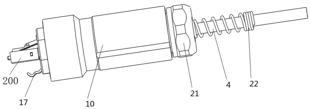
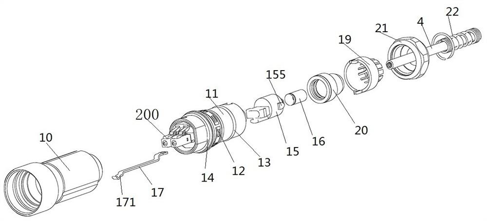
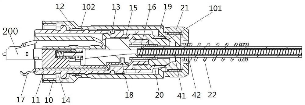
[0182] Such as Figure 1 to Figure 4 As shown, the optical fiber plug connector includes a plug housing and a plug inner core disposed inside the plug housing, and the plug inner core includes contacts. The front end of the plug housing is a plug-in end, and the plug-in end is used to connect with an adapter socket; the rear end of the plug housing is provided with an optical cable perforation for the optical cable 4 to penetrate and connect with the contact.
[0183] Such as Figure 2 to Figure 4 As shown, the plug housing includes an outer shell 10 and an inner sleeve 11. The inner sleeve 11 is inserted into the outer shell 10. There is a space between the front end of the inner sleeve 11 and the outer shell 10, and the space is used for the socket of the adapter socket. The housing is inserted. A positioning spring 12 is arranged between the outer shell 10 and the inner sleeve 11. The positioning spring 12 is a ring-shaped sheet structure with an opening. The shrapnel, t...
specific Embodiment 2
[0196] The main difference between it and the first embodiment of the optical fiber plug connector is that the conductive part and the support sleeve of the first embodiment of the optical fiber plug connector are fixedly connected by screws. Such as Figure 12 As shown, in this embodiment, a C-shaped claw 17001 is provided at the rear end of the conductive member 1700, and a C-shaped groove 15001 is provided on the outer peripheral surface of the support sleeve 1500. The C-shaped groove 15001 is adapted to the C-shaped claw 17001, and the C-shaped The elastic claw 17001 is hugged and fixed on the bottom of the C-shaped groove 15001 to realize the conductive connection between the conductive member 1700 and the supporting sleeve 1500 .
specific Embodiment 3
[0198] The main difference between it and the first embodiment of the optical fiber plug connector is that the conductive part and the support sleeve of the first embodiment of the optical fiber plug connector are fixedly connected by screws. Such as Figure 13 As shown, in this embodiment, two elastic arms are provided at the rear end of the conductive member 1701. One end of the two elastic arms is fixed, and the other end is spaced apart to form a U-shaped structure 17011 with an opening. The two elastic arms are provided at the opening position. For the hooks that are close to each other, grooves 15011 are provided on the outer peripheral surface of the support sleeve 1501 , and the grooves 15011 are adapted to the U-shaped structure 17011 . The two elastic arms are sleeved on the groove 15011 , and the two hooks are engaged with the groove bottom of the groove 15011 to realize the conductive connection between the conductive member 1701 and the supporting sleeve 1501 .
PUM
 Abstract
Description
Claims
Application Information
 - R&D
- Intellectual Property
- Life Sciences
- Materials
- Tech Scout
- Unparalleled Data Quality
- Higher Quality Content
- 60% Fewer Hallucinations
Browse by: Latest US Patents, China's latest patents, Technical Efficacy Thesaurus, Application Domain, Technology Topic, Popular Technical Reports.
© 2025 PatSnap. All rights reserved.Legal|Privacy policy|Modern Slavery Act Transparency Statement|Sitemap|About US| Contact US: help@patsnap.com


