Optical system, camera module and electronic equipment

An optical system, technology of relations, applied in the field of photography

Pending Publication Date: 2021-02-05
JIANGXI JINGCHAO OPTICAL CO LTD
View PDF0 Cites 4 Cited by
  • Summary
  • Abstract
  • Description
  • Claims
  • Application Information

AI Technical Summary

Problems solved by technology

[0004] Based on this, it is necessary to provide an optical system, camera module and electronic equipment for the problem of how to make the system have excellent camera performance and axial miniaturization design.

Method used


Image

  • Optical system, camera module and electronic equipment
  • Optical system, camera module and electronic equipment
  • Optical system, camera module and electronic equipment

Examples


no. 1 example

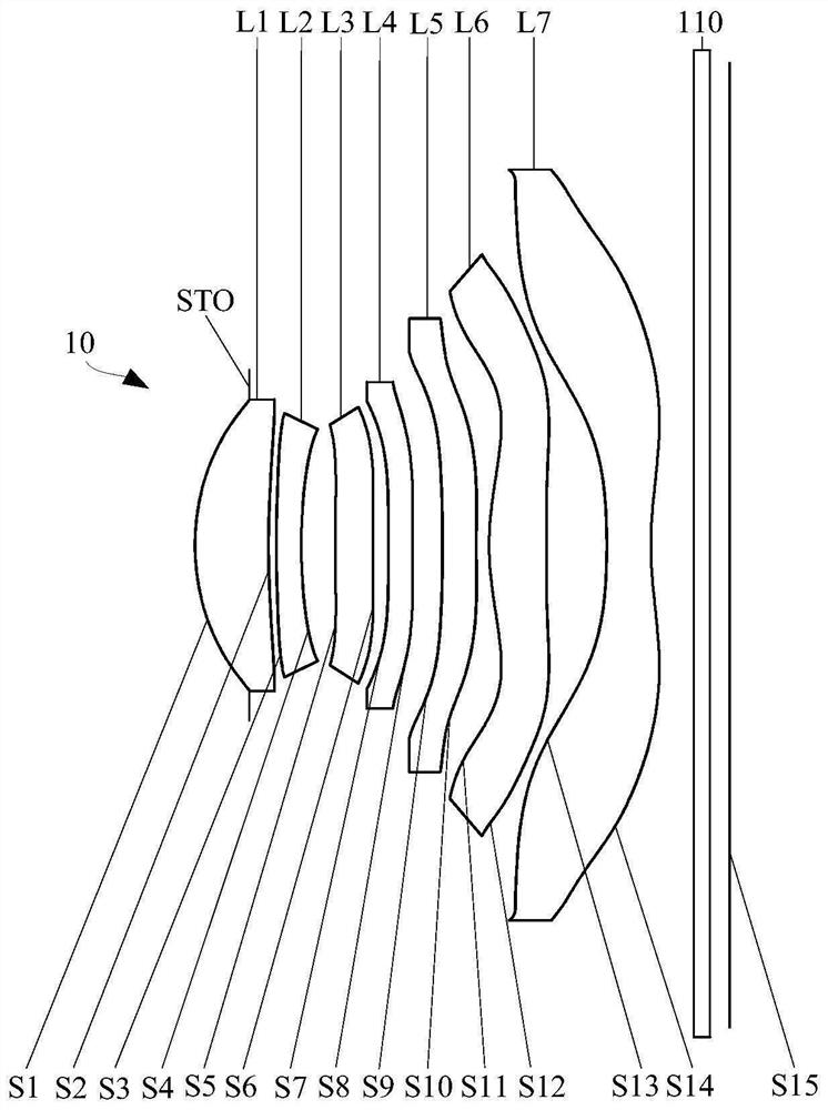
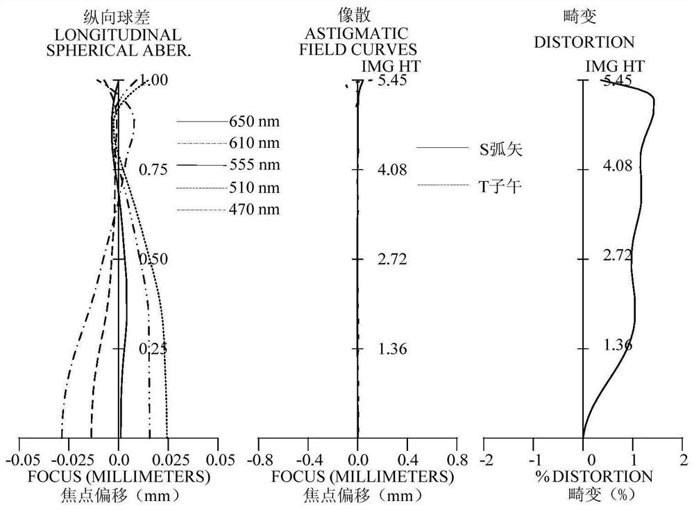
[0103] refer to figure 1 and figure 2 , in the first embodiment, the optical system 10 sequentially includes an aperture stop STO, a first lens L1 with positive refractive power, a second lens L2 with negative refractive power, and a second lens L2 with positive refractive power from the object side to the image side. Three lenses L3, a fourth lens L4 with positive refractive power, a fifth lens L5 with negative refractive power, a sixth lens L6 with positive refractive power, and a seventh lens L7 with negative refractive power. figure 2 It includes the longitudinal spherical aberration diagram, the astigmatism diagram and the distortion diagram of the optical system 10 in the first embodiment, wherein the reference wavelength of the astigmatism diagram and the distortion diagram is 555 nm.

[0104] The object side S1 of the first lens L1 is convex at the paraxial position, and the image side S2 is concave at the paraxial position; the object side S1 is convex at the circu...

no. 2 example

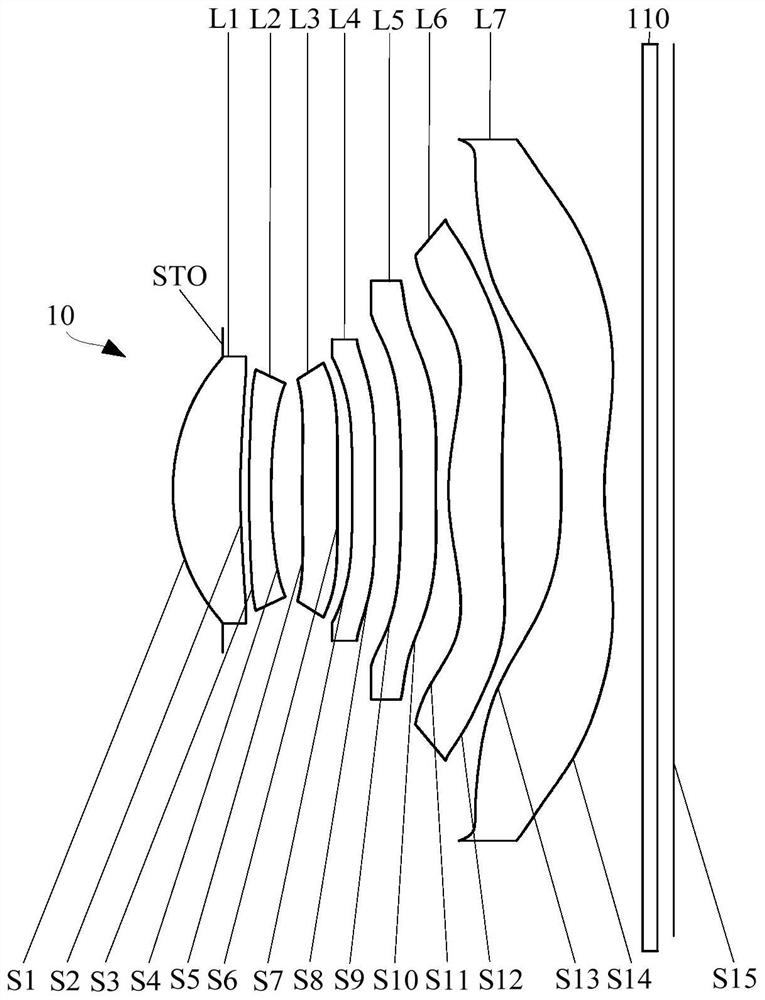
[0137] refer to image 3 and Figure 4 , in the second embodiment, the optical system 10 includes an aperture stop STO, a first lens L1 with positive refractive power, a second lens L2 with negative refractive power, and a first lens L2 with positive refractive power from the object side to the image side. Three lenses L3, a fourth lens L4 with negative refractive power, a fifth lens L5 with negative refractive power, a sixth lens L6 with positive refractive power, and a seventh lens L7 with negative refractive power. Figure 4 It includes the longitudinal spherical aberration diagram, the astigmatism diagram and the distortion diagram of the optical system 10 in the second embodiment, wherein the reference wavelength of the astigmatism diagram and the distortion diagram is 555 nm.

[0138] The object side S1 of the first lens L1 is convex at the paraxial position, and the image side S2 is concave at the paraxial position; the object side S1 is convex at the circumference, an...

no. 3 example

[0155] refer to Figure 5 and Figure 6 , in the third embodiment, the optical system 10 includes an aperture stop STO, a first lens L1 with positive refractive power, a second lens L2 with negative refractive power, and a second lens L2 with negative refractive power from the object side to the image side. Three lenses L3, a fourth lens L4 with positive refractive power, a fifth lens L5 with negative refractive power, a sixth lens L6 with positive refractive power, and a seventh lens L7 with negative refractive power. Figure 6 It includes the longitudinal spherical aberration diagram, the astigmatism diagram and the distortion diagram of the optical system 10 in the third embodiment, wherein the reference wavelength of the astigmatism diagram and the distortion diagram is 555 nm.

[0156] The object side S1 of the first lens L1 is convex at the paraxial position, and the image side S2 is concave at the paraxial position; the object side S1 is convex at the circumference, an...


PUM


Abstract

The invention relates to an optical system, a camera module and electronic equipment. The optical system includes, in order from an object side to an image side: a first lens element which has positive refractive power and has a convex object-side surface at a paraxial region and a concave image-side surface at a paraxial region; a second lens element which has negative refractive power and has aconvex object-side surface at a paraxial region and a concave image-side surface at a paraxial region; a third lens element, a fourth lens element, a fifth lens element and a sixth lens element whichall have refractive power; and a seventh lens element which has negative refractive power and has a concave image-side surface at a paraxial region. The system meets the following relationship: Imgh2 / (TTL*Fno) is greater than or equal to 2.3 mm, wherein Imgh is half of the image height corresponding to the maximum field angle of the optical system, TTL is the distance between the object side surface of the first lens and the imaging surface of the optical system on an optical axis, and Fno is the aperture number of the optical system. The optical system has excellent camera shooting performance and axial miniaturization design.

Description

technical field [0001] The invention relates to the technical field of photography, in particular to an optical system, a camera module and electronic equipment. Background technique [0002] With the upgrading of technology, consumers have higher and higher requirements for the shooting quality of mobile electronic products. In general, the seven-chip camera lens has obvious advantages and can obtain higher resolution, so it is often used in high-end mobile electronic products to improve the image quality, resolution and clarity of shooting. [0003] But for general electronic products, the market often hopes that electronic products can not only have excellent camera performance, but also reduce the thickness as much as possible. However, for a camera lens with a seven-piece structure, due to the large number of lenses, it is often difficult to reduce the axial size of this type of lens system, and it is difficult to maintain a short length while satisfying excellent came...

Claims


Application Information

Patent Timeline
Patent Type & Authority Applications(China)
IPC IPC(8): G02B13/00G02B13/18
CPCG02B13/0045
Inventor 徐标李明
Owner JIANGXI JINGCHAO OPTICAL CO LTD
Why Eureka
Try Eureka