
Plug connector and connector assembly

A technology of plug connectors and conductive parts, which is applied to the parts, connections, and two-part connection devices of connection devices, etc. It can solve problems such as difficult control, high requirements for plug sleeve installation, and complicated plug sleeve structure, and achieve simplification. Structure, guaranteed grounding or shielding effect, guaranteed close contact effect

Pending Publication Date: 2021-02-05
CHINA AVIATION OPTICAL-ELECTRICAL TECH CO LTD
View PDF0 Cites 2 Cited by
  • Summary
  • Abstract
  • Description
  • Claims
  • Application Information

AI Technical Summary

Problems solved by technology

[0010] The purpose of the present invention is to provide a plug connector to solve the complex structure of the plug sleeve caused by the need to provide a tightening structure in the plug sleeve in the prior art, and the control of shielding by the degree of screwing in of the plug sleeve in the prior art. The conductive parts are in close contact with the conductive shell at the front end of the plug, which leads to high installation requirements and difficult control of the plug sleeve
The object of the present invention is also to provide a connector assembly to solve the problem of complex structure of the plug sleeve due to the need to provide a tightening structure in the plug sleeve in the prior art, and the control of the screwing degree of the plug sleeve in the prior art. The shielding conductive part is in close contact with the conductive shell at the front end of the plug, which leads to high installation requirements and difficult control of the plug sleeve

Method used

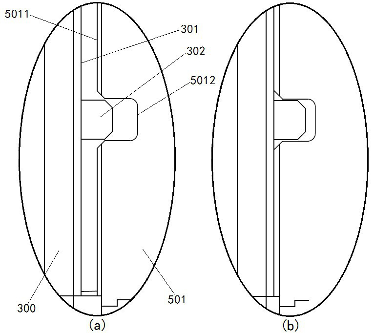
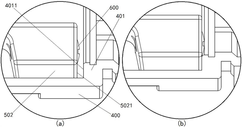

Image

  • Plug connector and connector assembly
  • Plug connector and connector assembly
  • Plug connector and connector assembly

Examples


Embodiment Construction

[0067]In order to make the objectives, technical solutions and advantages of the present invention clearer, the following further describes the present invention in detail with reference to the accompanying drawings and embodiments. It should be understood that the specific embodiments described here are only used to explain the present invention and not to limit the present invention, that is, the described embodiments are only a part of the embodiments of the present invention, rather than all the embodiments. The components of the embodiments of the present invention generally described and illustrated in the drawings herein may be arranged and designed in various different configurations.

[0068]Therefore, the following detailed description of the embodiments of the present invention provided in the accompanying drawings is not intended to limit the scope of the claimed invention, but merely represents selected embodiments of the present invention. Based on the embodiments of the ...


PUM


Abstract

The invention provides a plug connector and a connector assembly. The plug connector comprises: an inner-layer conductive shell; a tail sleeve; a first insulator, wherein a power supply conductive part is arranged in the first insulator, the power supply conductive part comprises a plug contact piece, a second insulator and an elastic washer are arranged outside the plug contact piece, the elasticwasher is in stop fit with the front end surface of the first insulator, and an annular flange is arranged on the outer surface of the first insulator; a shielding conductive part, wherein the frontend of the shielding conductive part is provided with a conductive sheet in stop fit with the annular flange; and a snap spring which is positioned on the rear side of the conductive sheet. The inner-layer conductive shell is provided with a stop step and an annular clamping groove, the distance between the stop step and the annular clamping groove meets the requirement that after the clamping spring is clamped into the clamping groove, the elastic washer is compressed to apply backward acting force to the first insulator, and the annular flange abuts against the conductive sheet on the end face of the clamping spring. A jacking structure does not need to be arranged on the tail sleeve, the structure of the tail sleeve can be simplified, meanwhile, during installation, only the clamping spring needs to be clamped into the annular clamping groove through a tool, and installation is convenient.

Description

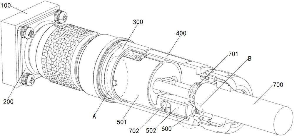
Technical field[0001]The invention relates to the technical field of connectors, in particular to a plug connector and a connector assembly.Background technique[0002]When the chassis cabinet is grounded or shielded, it is necessary to connect the connector of the chassis cabinet interface to the chassis cabinet panel to realize the conduction between the shielding layer of the cable connected to the connector and the panel, thereby achieving the grounding or shielding effect of the entire link.[0003]The connection form of the connector assembly in the prior art is as followsfigure 1 As shown, the connector assembly includes a plug connector and a socket connector. The socket connector includes a socket conductive shell 200 fixed on the cabinet panel 100, and the plug connector includes a plug front end that is conductively mated with the socket conductive shell 200. The conductive housing 300 and the plug sleeve 400 screwed to the rear end of the conductive housing 300 at the front ...

Claims


Application Information

Patent Timeline
Patent Type & Authority Applications(China)
IPC IPC(8): H01R13/6591H01R13/6581H01R24/30H01R24/78
CPCH01R13/6581H01R13/6591H01R24/30H01R24/78
Inventor 王恒刘向阳许蔚李立新张志中韩云钊李卫可武学顺徐耕邹宏飞全硒硼柳先波田旭习冰寒闫丰献胡竣浩
Owner CHINA AVIATION OPTICAL-ELECTRICAL TECH CO LTD
Learn More