Fixing device for bicycle part production and machining

A technology for fixing devices and parts, applied in positioning devices, metal processing equipment, metal processing machinery parts, etc., can solve the problems of worker injury, increased workload, low efficiency, etc., and achieve the effect of stable clamping and fixing

Inactive Publication Date: 2021-02-09
广州华百教育咨询有限公司
View PDF0 Cites 2 Cited by
  • Summary
  • Abstract
  • Description
  • Claims
  • Application Information

AI Technical Summary

Problems solved by technology

[0003] The body of a bicycle includes many parts, such as pedals, brake handles, brake pads and chainrings, etc. These parts need to be drilled, polished or cut during processing. The current processing methods are generally Workers hold processing equipment and parts for processing, or hold parts close to fixed processing equipment for processing, and processing equipment may cause damage to workers' hands, and parts may fall off or pop out due to negligence during processing The situation affects the processing effect and requires reprocessing, which increases the workload and has certain safety hazards; and these parts are mostly irregular parts, and generally processing equipment with clamping devices can only process parts with regular shapes. Processing, if this kind of equipment is used to process irregular parts, not only the efficiency is low but the clamping is not stable enough, which will affect the processing results
[0004] Aiming at the deficiencies of the prior art, the present invention provides a fixing device for the production and processing of bicycle parts, which has the advantages of automatically clamping and fixing the parts, is applicable to parts of various shapes, and has more stable clamping, and solves the problem of Hand-held parts processing by workers has potential safety hazards, and the application range of general processing equipment is small

Method used


Image

  • Fixing device for bicycle part production and machining
  • Fixing device for bicycle part production and machining
  • Fixing device for bicycle part production and machining

Examples


Embodiment Construction

[0026] The following will clearly and completely describe the technical solutions in the embodiments of the present invention with reference to the accompanying drawings in the embodiments of the present invention. Obviously, the described embodiments are only some, not all, embodiments of the present invention. Based on the embodiments of the present invention, all other embodiments obtained by persons of ordinary skill in the art without making creative efforts belong to the protection scope of the present invention.

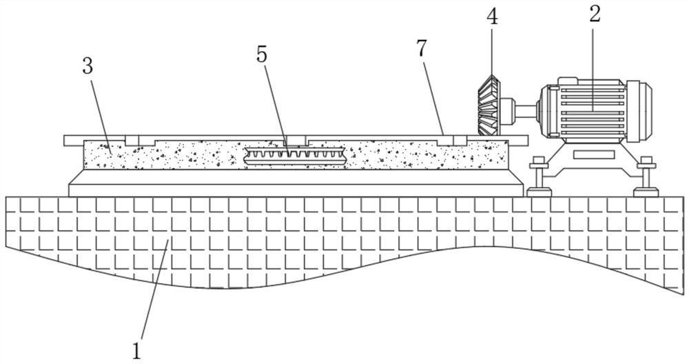
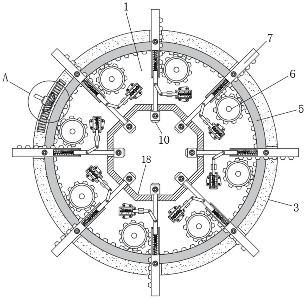
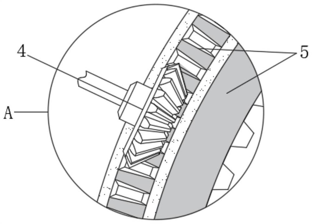
[0027] see Figure 1-6 , a fixing device for the production and processing of bicycle parts, comprising an operating table 1, the upper end of the operating table 1 is respectively fixedly connected with a motor 2 and an outer limit ring 3, and the upper surface of the operating table 1 is fixedly connected with an inner limit ring 18, The inner limit ring 18 is octagonal, the diameter is smaller than the outer limit ring 3, and is concentric with the outer li...


PUM


Abstract

The invention relates to the technical field of bicycle parts, and discloses a fixing device for bicycle part production and machining. The fixing device comprises an operation table, wherein a motorand an outer limiting ring are fixedly connected to the upper end of the operation table, a bevel gear is arranged on an output shaft of the motor, and a gear ring is rotatably connected to the interior of the outer limiting ring; and circular gears are connected to the tooth edge of the inner ring of the gear ring in a meshed mode, and racks are connected to the tooth edges of the circular gearsin a meshed mode. According to the fixing device for bicycle part production and machining, when clamping blocks abut against a part, the clamping blocks stop moving, the racks are driven by the circular gears to continue to move at the moment, spring rods are compressed at the moment, switch assemblies in the spring rods abut against the clamping blocks, a circuit is closed, and electrorheological fluid is powered on to be in a solid state; and guide rods are limited, the guide rods cannot continue to move, thus, push rods and the clamping blocks cannot move, and the effect that the part is clamped and fixed more stably is achieved.

Description

technical field [0001] The invention relates to the technical field of bicycle parts, in particular to a fixing device for the production and processing of bicycle parts. Background technique [0002] Bicycles, also known as bicycles or bicycles, are one of the common green and environmentally friendly means of transportation in life. Due to the characteristics of economical and convenient use of bicycles, people in modern society use bicycles as short-distance transportation, exercise or travel. [0003] The body of a bicycle includes many parts, such as pedals, brake handles, brake pads and chainrings, etc. These parts need to be drilled, polished or cut during processing. The current processing methods are generally Workers hold processing equipment and parts for processing, or hold parts close to fixed processing equipment for processing, and processing equipment may cause damage to workers' hands, and parts may fall off or pop out due to negligence during processing Th...

Claims


Application Information

Patent Timeline
IPC IPC(8): B23Q3/06
CPCB23Q3/06
Inventor 杨辉
Owner 广州华百教育咨询有限公司
Why Eureka
Try Eureka