A rail vehicle anti-skid control method, device and rail vehicle system
A technology of a rail vehicle and a control method, applied in the field of rail vehicles, can solve the problems that the wheels cannot run in the optimal slip rate range, the wheels cannot run all the time, etc., and achieve the effect of avoiding sliding
- Summary
- Abstract
- Description
- Claims
- Application Information
AI Technical Summary
Problems solved by technology
Method used
Image

Examples
Embodiment 1
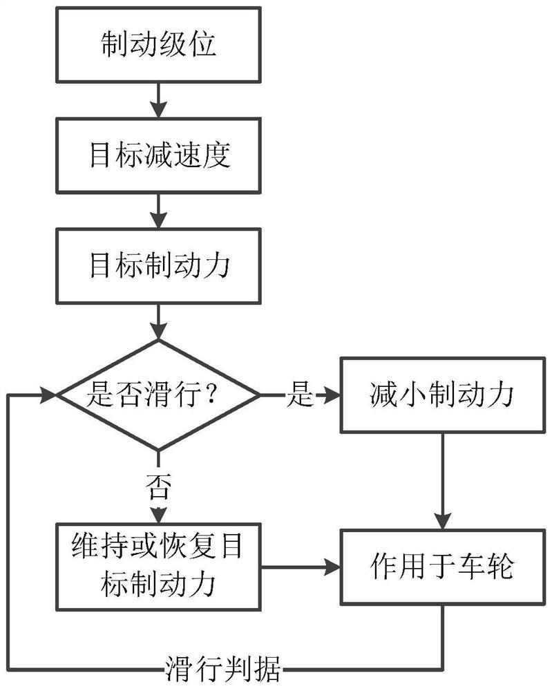
[0045] Figure 5 A schematic flowchart of the implementation of the anti-skid control method for a rail vehicle in Embodiment 1 of the present application is shown.
[0046] As shown in the figure, the anti-skid control method for a rail vehicle includes:
[0047] Step 501, obtain the vehicle target deceleration a according to the given braking level; And, obtain the current deceleration a' of the controlled shaft according to the shaft speed of the controlled shaft;
[0048] Step 502, obtain the deceleration difference Δa according to the target deceleration a and the current deceleration a';
[0049] Step 503: Generate a braking force change command according to the deceleration difference Δa and the pre-calculated slip ratio S of the controlled shaft.
[0050] During specific implementation, the braking level of the rail vehicle system may include levels 1-7, and the braking level may be determined according to the braking level instruction obtained by the driver or other...
Embodiment 2
[0120] Based on the same inventive concept, the embodiments of the present application provide an anti-skid control device for a rail vehicle. The principle of these devices for solving the technical problem is similar to a method for anti-skid control of a rail vehicle, and the repetition will not be repeated.
[0121] Figure 9 A schematic structural diagram of the anti-skid control device for a rail vehicle in the second embodiment of the present application is shown.
[0122] As shown in the figure, the rail vehicle anti-skid control device includes:
[0123] The target deceleration module 901 is used to obtain the vehicle target deceleration a according to the given braking level;
[0124] a deceleration module 902, configured to obtain the current deceleration a' of the controlled shaft according to the shaft speed of the controlled shaft;
[0125] A deceleration difference value module 903, configured to obtain a deceleration difference value Δa according to the targe...
Embodiment 3
[0155] Based on the same inventive concept, the embodiments of the present application provide a rail vehicle system, which will be described below.
[0156] Figure 10 A schematic structural diagram of the rail vehicle system in the third embodiment of the present application is shown.
[0157] As shown in the figure, the rail vehicle system includes: a train control network system 1001, the rail vehicle anti-skid control device 1002 described in the second embodiment, and a braking system 1003;
[0158] in,
[0159]The train control network system is used to give the braking level;
[0160] The braking system is used for changing the braking force acting on the controlled axle under the control of the rail vehicle anti-skid control device.
[0161] In one embodiment, the braking system includes one or more of the following:
[0162] Air brake system, hydraulic brake system, electric brake system.
PUM
 Abstract
Description
Claims
Application Information
 - R&D
- Intellectual Property
- Life Sciences
- Materials
- Tech Scout
- Unparalleled Data Quality
- Higher Quality Content
- 60% Fewer Hallucinations
Browse by: Latest US Patents, China's latest patents, Technical Efficacy Thesaurus, Application Domain, Technology Topic, Popular Technical Reports.
© 2025 PatSnap. All rights reserved.Legal|Privacy policy|Modern Slavery Act Transparency Statement|Sitemap|About US| Contact US: help@patsnap.com