
Photoelectric sensor transportation device suitable for uneven road sections and using method

A photoelectric sensor and transportation device technology, applied in transportation and packaging, non-removable covers/covers, containers to prevent mechanical damage, etc., can solve problems such as box bumps, photoelectric sensor damage, single function, etc., to improve transportation efficiency , to ensure stability, to prevent the effect of shifting

Inactive Publication Date: 2021-02-09
朱小松
View PDF20 Cites 1 Cited by
  • Summary
  • Abstract
  • Description
  • Claims
  • Application Information

AI Technical Summary

Problems solved by technology

Its working principle is based on the photoelectric effect. It first converts the measured changes into changes in optical signals, and then further converts the optical signals into electrical signals with the help of photoelectric elements. At present, most photoelectric sensors are stored and transported in transfer boxes when they are transported. Some transfer boxes have a single function. They only separate multiple photoelectric sensors through multiple partitions pre-placed in the box, and do not effectively limit and fix the photoelectric sensors, and the box will bump during transportation. Phenomenon, strong vibration is easy to cause damage to the photoelectric sensor and affect the service life of the photoelectric sensor. Therefore, a photoelectric sensor transportation device and usage method suitable for uneven roads are of great practical value.

Method used


Image

  • Photoelectric sensor transportation device suitable for uneven road sections and using method
  • Photoelectric sensor transportation device suitable for uneven road sections and using method
  • Photoelectric sensor transportation device suitable for uneven road sections and using method

Examples


Embodiment Construction

[0023] The following will clearly and completely describe the technical solutions in the embodiments of the present invention with reference to the accompanying drawings in the embodiments of the present invention. Obviously, the described embodiments are only some, not all, embodiments of the present invention. Based on the embodiments of the present invention, all other embodiments obtained by persons of ordinary skill in the art without making creative efforts belong to the protection scope of the present invention.

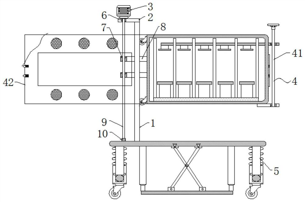
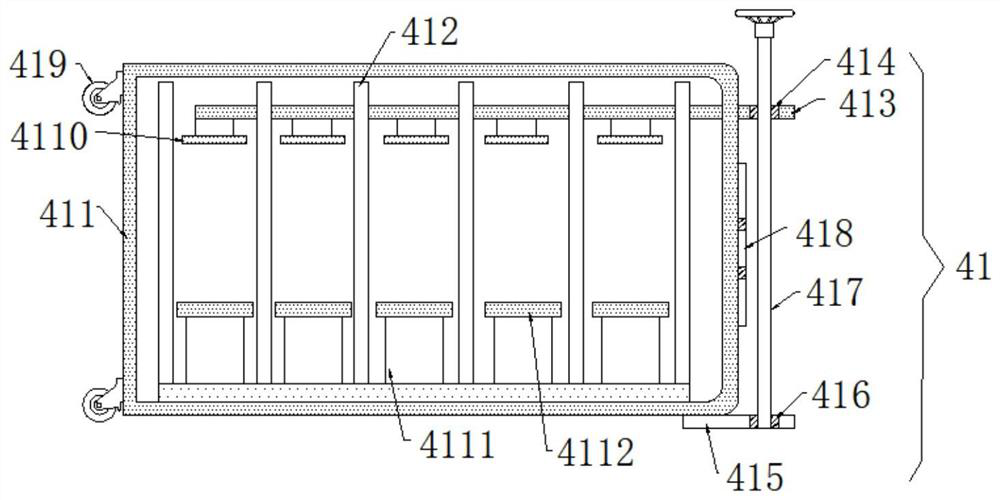
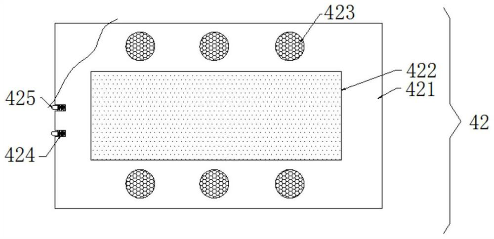
[0024] see figure 1 , the present invention provides a technical solution for a photoelectric sensor transportation device suitable for uneven road sections: a photoelectric sensor transportation device suitable for uneven road sections, including a vertical board 1, the top of the vertical board 1 is fixedly connected with a horizontal board 2, and the horizontal board 2 The top of the horizontal plate 2 is connected with a deceleration motor 3, the decelerat...


PUM


Abstract

The invention discloses a photoelectric sensor transportation device suitable for uneven road sections and a using method, and belongs to the technical field of photoelectric sensors. The photoelectric sensor transportation device comprises a vertical plate, a transverse plate is fixedly connected to the top of the vertical plate, a gear motor is connected to the top of the transverse plate, and ascrew rod is arranged on the gear motor; a mounting hole is longitudinally formed at the top of the transverse plate in a penetrating manner, a first bearing matched with the screw rod is fixedly connected to an inner cavity of the mounting hole, the periphery of the screw rod is sleeved with a plurality of sets of first threaded sleeves, and a transportation bottom plate is arranged at the bottom of the vertical plate; and the photoelectric sensor transportation device can conduct damping and buffering treatment on jolt generated in the transportation process, so that it is guaranteed that aphotoelectric sensor is not damaged by jolt vibration in the transportation process, the service life of the photoelectric sensor is prolonged, meanwhile, the photoelectric sensor transportation device can conduct clamping and fixing treatment on the photoelectric sensor in the transportation process, and the photoelectric sensor is prevented from sliding in the transportation process and being collided and damaged, so that the photoelectric sensor is protected.

Description

technical field [0001] The invention relates to the technical field of photoelectric sensors, in particular to a transportation device for photoelectric sensors suitable for uneven road sections and a method for using them. Background technique [0002] A photoelectric sensor is a device that converts light signals into electrical signals. Its working principle is based on the photoelectric effect. It first converts the measured changes into changes in optical signals, and then further converts the optical signals into electrical signals with the help of photoelectric elements. At present, most photoelectric sensors are stored and transported in transfer boxes when they are transported. Some transfer boxes have a single function. They only separate multiple photoelectric sensors through multiple partitions pre-placed in the box, and do not effectively limit and fix the photoelectric sensors, and the box will bump during transportation. Phenomenon, strong vibration can easil...

Claims


Application Information

Patent Timeline
Patent Type & Authority Applications(China)
IPC IPC(8): B65D25/10B65D25/24B65D43/16B65D55/10B65D81/05B65D85/30B65D85/86F16F15/04F16F15/067B65D25/02B60B33/00
CPCB65D25/10B65D25/02B65D25/24B65D43/166B65D55/10B65D81/05B65D85/30F16F15/04F16F15/067B60B33/0002B65D2585/86
Inventor 朱小松
Owner 朱小松
Learn More