Elevated steel-concrete composite beam

A technology for steel-concrete composite beams and steel beams, applied in the field of composite beams, can solve problems such as bending of bottom support rods

Active Publication Date: 2021-02-09
GUIZHOU ROAD & BRIDGE GRP
View PDF6 Cites 0 Cited by
  • Summary
  • Abstract
  • Description
  • Claims
  • Application Information

AI Technical Summary

Problems solved by technology

[0005] The purpose of the present invention is to provide an elevated steel-concrete composite beam to solve the problem that the support rods at the bottom of the prior art cannot carry o

Method used


Image

  • Elevated steel-concrete composite beam
  • Elevated steel-concrete composite beam

Examples


Embodiment Construction

[0019] The following will clearly and completely describe the technical solutions in the embodiments of the present invention with reference to the accompanying drawings in the embodiments of the present invention. Obviously, the described embodiments are only some, not all, embodiments of the present invention. Based on the embodiments of the present invention, all other embodiments obtained by persons of ordinary skill in the art without making creative efforts belong to the protection scope of the present invention.

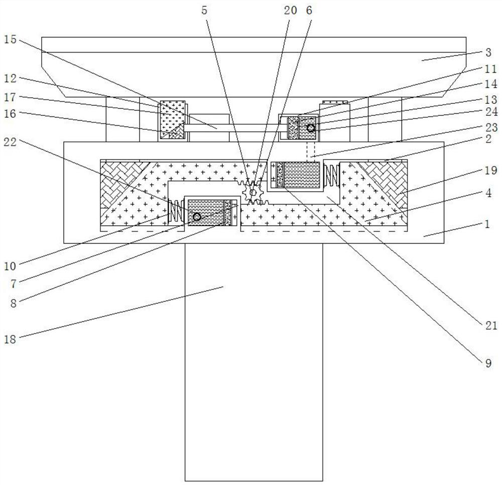
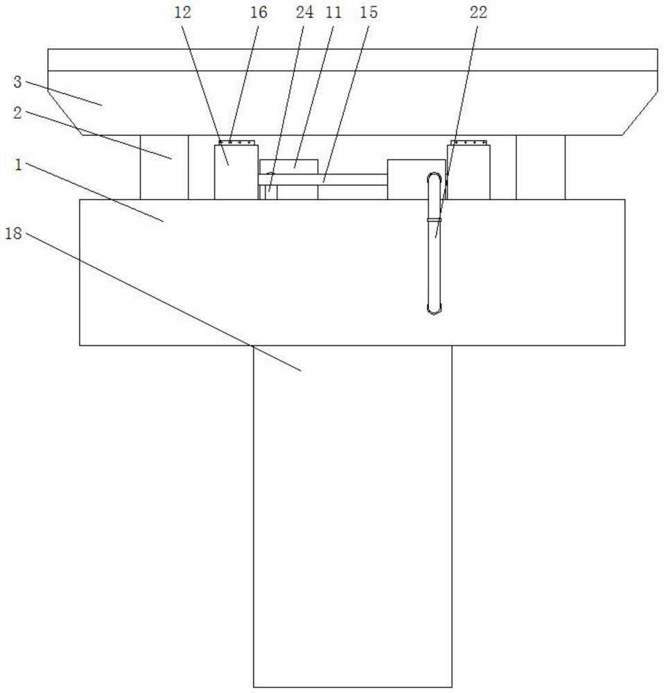
[0020] see Figure 1-2, an embodiment provided by the present invention: an elevated steel-concrete composite beam, comprising a beam 1 and a pier column 18, the beam 1 is fixedly connected to the top of the pier column 18, and both sides of the bottom of the inner wall of the beam 1 slide Connect the transmission seat 4, the sliding seat 19 is slidably connected to the separated sides of the two transmission seats 4, and the tops of the two sliding seats 19 a...


PUM


Abstract

The invention discloses an elevated steel-concrete composite beam which comprises a cross beam and a pier stud, the cross beam is fixedly connected to the top of the pier stud, transmission bases areslidably connected to the two sides of the bottom of the inner wall of the cross beam, sliding bases are slidably connected to the sides, away from each other, of the two transmission bases, and steelbeams are fixedly connected to the tops of the two sliding bases. The tops of the two steel beams penetrate through the cross beam and extend to the position above the cross beam, a concrete plate isfixedly connected between the tops of the two steel beams, rectangular grooves are formed in the bottom of one transmission base and the top of the other transmission base, and the two transmission bases are symmetrically connected to the bottom of the inner wall of the cross beam in a staggered and sliding mode. The two sides of the bottom of the concrete slab are stressed at the same time and do not descend any more, the force is decomposed and converted, the situation that the concrete slab is stressed unevenly is reduced, the stability of the overall structure of the concrete beam is improved, the underpinning is in a straight rod shape, longitudinal and horizontal stress is conducted, and the bending phenomenon is avoided.

Description

technical field [0001] The invention relates to the technical field of composite beams, in particular to an elevated steel-concrete composite beam. Background technique [0002] Steel-concrete composite beam is a new type of structure developed on the basis of steel structure and concrete structure. It mainly resists the lifting and relative slippage at the interface between the steel beam and the concrete flange plate by setting shear connectors (bolts, channel steel, bending bars, etc.), making it a whole work together. [0003] At present, the existing elevated steel-concrete composite beams fix the steel beam and the concrete slab together through shear connectors. When one side of the top of the concrete slab is tilted under force, if it cannot be adjusted and reset, the force will be applied for a long time, which will cause the steel Cracks occur at the joint between the beam and the concrete slab, which may lead to fracture for a long time. The pillars at the botto...

Claims


Application Information

Patent Timeline
IPC IPC(8): E01D19/00
CPCE01D19/00Y02A30/30
Inventor 曾斌陈建伟刘向琼刘常军王钢郝世国谷告柏黄鑫纪海成曹凯
Owner GUIZHOU ROAD & BRIDGE GRP
Why Eureka
Try Eureka