Staggered deceleration strip power generation equipment based on hydraulic drive

A technology of power generation equipment and speed bumps, which is applied to mechanical equipment, mechanisms that generate mechanical power, traffic signals, etc., can solve the problems of inability to use the kinetic energy of passing vehicles in a safe and effective way, and aggravate energy problems, so as to ensure driving comfort, Strong retreatability and the effect of improving energy recovery rate

Active Publication Date: 2021-02-09
HUAZHONG UNIV OF SCI & TECH
View PDF11 Cites 0 Cited by
  • Summary
  • Abstract
  • Description
  • Claims
  • Application Information

AI Technical Summary

Problems solved by technology

[0003] In order to ensure safe driving, a large number of traffic guidance and lighting facilities need to be installed in expressways, toll stations, urban roads, tunnels and other places, which brings a lot of power consumption and further exacerbates the increasingly serious energy problem
On the other hand, the average daily traffic flow in the above-mentioned traffic places is huge, and the speed bump is a kind of traffic facility set up to ensure the safety of pedestrians. The amount of power generated by using the kinetic energy lost when the vehicle passes through the speed bump is also very considerable. Therefore, It is of great significance to convert vehicle kinetic energy into electrical energy to realize the self-sufficiency of traffic system power, but the existing road deceleration devices cannot effectively utilize the kinetic energy of passing vehicles while ensuring driving comfort and safety

Method used


Image

  • Staggered deceleration strip power generation equipment based on hydraulic drive
  • Staggered deceleration strip power generation equipment based on hydraulic drive
  • Staggered deceleration strip power generation equipment based on hydraulic drive

Examples


Embodiment Construction

[0029] In order to make the object, technical solution and advantages of the present invention clearer, the present invention will be further described in detail below in conjunction with the accompanying drawings and embodiments. It should be understood that the specific embodiments described here are only used to explain the present invention, not to limit the present invention. In addition, the technical features involved in the various embodiments of the present invention described below can be combined with each other as long as they do not constitute a conflict with each other.

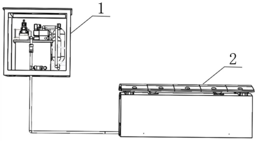
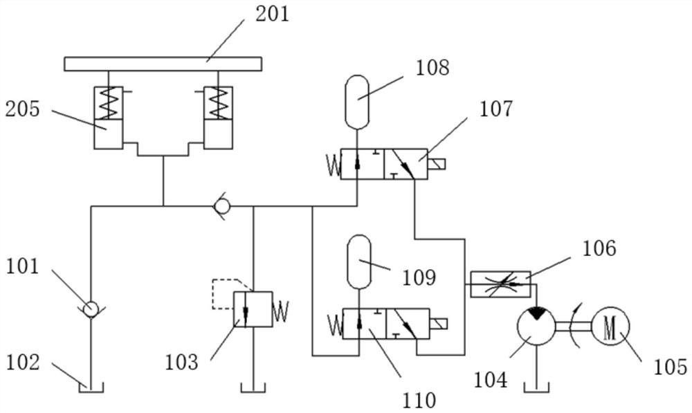
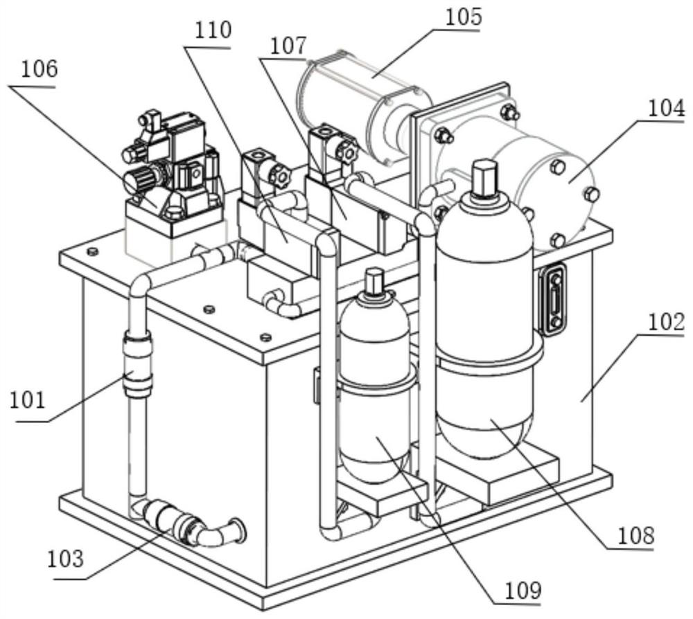
[0030] see figure 1 , figure 2 and image 3 , the present invention provides hydraulically driven staggered deceleration belt power generation equipment, the power generation equipment includes a deceleration belt main body 2, a hydraulic workstation 1 and a circuit system, the deceleration belt main body 2 is connected to the hydraulic workstation 1, and the circuit The system is connected ...


PUM


Abstract

The invention belongs to the related technical field of deceleration strip power generation equipment, and discloses staggered deceleration strip power generation equipment based on hydraulic drive. The staggered deceleration strip power generation equipment comprises a deceleration strip body and a hydraulic workstation communicating with the deceleration strip body. The hydraulic workstation comprises a first energy accumulator, a first electromagnetic reversing valve, a second energy accumulator and a second electromagnetic reversing valve, the first electromagnetic reversing valve is connected with the first energy accumulator to form a first energy accumulation assembly, the second energy accumulator is connected with the second electromagnetic reversing valve to form a second energyaccumulation assembly, and the first energy accumulation assembly is connected with the second energy accumulation assembly in parallel. The first energy accumulator and the second energy accumulatorwork alternately to realize continuous energy charging and power generation. The deceleration strip body comprises a deceleration strip, a plurality of hydraulic cylinders and hydraulic dampers, the hydraulic cylinders and the hydraulic dampers are separately connected to the deceleration strip, and the hydraulic cylinders and the hydraulic dampers are arranged in a staggered mode and jointly usedfor supporting the deceleration strip. According to the staggered deceleration strip power generation equipment based on the hydraulic drive, the energy recovery efficiency and applicability are improved, and the structure is simple.

Description

technical field [0001] The invention belongs to the related technical field of deceleration belt power generation equipment, and more specifically relates to a hydraulically driven staggered deceleration belt power generation equipment. Background technique [0002] With the development of the economy and the improvement of living standards, the mileage of highways and the total number of vehicles on the road are increasing day by day. For example, the total mileage of highways in China has reached 4.85 million kilometers, and the number of vehicles on the road is increasing. By the end of 2019, the number of civilian vehicles in the country has reached There were 261.5 million vehicles, an increase of 21.22 million over the same period last year, of which the number of private cars was 226.35 million, an increase of 19.05 million, and the number of civilian cars was 146.44 million, an increase of 11.93 million. [0003] In order to ensure safe driving, a large number of tra...

Claims


Application Information

Patent Timeline
Patent Type & Authority Applications(China)
IPC IPC(8): F03G7/08E01F9/529
CPCF03G7/08E01F9/529
Inventor 吴志刚朱嘉淇雍昊臣黄炳康
Owner HUAZHONG UNIV OF SCI & TECH
Why Eureka
Try Eureka