
Sensor pressure detection tool

A technology for detecting tooling and sensors, which is applied in the field of sensor detection, and can solve problems such as easy displacement, low data accuracy, and sliding displacement

Inactive Publication Date: 2021-02-09
湖州智禾科技有限公司
View PDF0 Cites 2 Cited by
  • Summary
  • Abstract
  • Description
  • Claims
  • Application Information

AI Technical Summary

Problems solved by technology

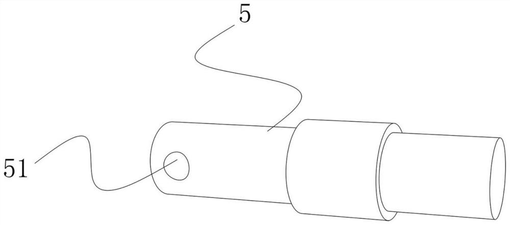
Moreover, the sensor is not fixed by other objects during the test, and it is prone to displacement and other phenomena, especially if the figure 1 The sensor with the structure shown is in the form of a cylinder as a whole. When the cylinder is clamped on the surface of the equipment, it is in linear contact with the surface of the equipment during the pressing process, and it is easy to slide and shift to one side, which leads to the detection of less accurate data

Method used


Image

  • Sensor pressure detection tool
  • Sensor pressure detection tool
  • Sensor pressure detection tool

Examples


Embodiment 1

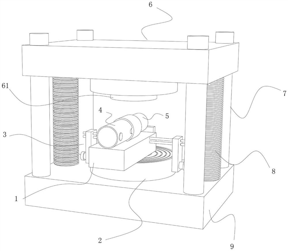
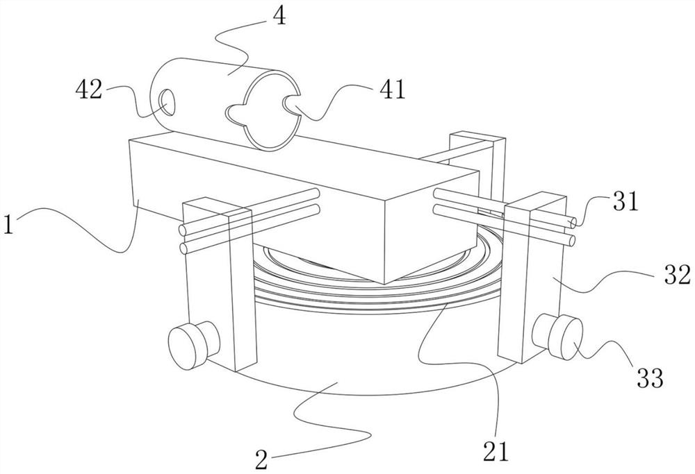
[0025] With reference to the accompanying drawings of the description of the present invention Figure 1 to Figure 5 As shown, a sensor pressure detection tooling according to a preferred embodiment of the present invention is illustrated, including a workbench 2 arranged on a machine base 9, a pressing assembly 6 and a detection assembly for loading a sensor 5, the workbench 2 Located below the top pressing assembly 6, the workbench 2 or the top pressing assembly 6 is movably arranged on the machine base 9 and can move up or down relative to the machine base 9, the detection assembly is detachably arranged on the workbench 2, the top pressing The assembly 6 includes a pressing head 61, and the pressing head 61 is located directly above the workbench 2; when in use, the workbench 2 or the pressing assembly 6 moves toward the other side, clamping the sensor 5 loaded in the detection assembly to detect the sensor The range of pressure that 5 can withstand, this technical solutio...


PUM


Abstract

The invention relates to a sensor pressure detection tool. The tool comprises a workbench arranged on a machine base, a coping assembly and a detection assembly used for loading a sensor. The workbench is located below the coping assembly, the workbench or the coping assembly is movably arranged on the machine base and can move upwards or downwards relative to the machine base, and the detection assembly is detachably arranged on the workbench; the coping assembly comprises a pressing head, and the pressing head is located over the workbench. During use, the workbench or the coping assembly moves towards the other side to clamp the sensor loaded in the detection assembly so as to detect the pressure range borne by the sensor; and the situation that the whole body deviates is prevented.

Description

technical field [0001] The invention relates to the technical field of sensor detection, in particular to a sensor pressure detection tool. Background technique [0002] When the sensor is performing a simulation test, the sensor will be placed on the test platform of the testing machine, and then the test pressure column will press down on the pressure position of the sensor, so as to output the conduction signal of the sensor. However, this type of test requires that the test site of the sensor be placed on the test platform at the bottom of the test pressure column. Often times the sensor needs to be adjusted several times while it is placed on the test bench. Moreover, the sensor is not fixed by other objects during the test, and it is prone to displacement and other phenomena, especially if the figure 1 The sensor with the structure shown is in the form of a cylinder as a whole. When the cylinder is clamped on the surface of the equipment, it is in linear contact with...

Claims


Application Information

Patent Timeline
Patent Type & Authority Applications(China)
IPC IPC(8): G01L25/00G01L27/00
CPCG01L25/00G01L27/00
Inventor 王颖杰
Owner 湖州智禾科技有限公司
Learn More