
Wafer rotation speed detection device

A rotational speed detection and wafer technology, which is applied to devices, electrical components, circuits, etc. using optical methods, can solve problems such as poor sealing effect of the inner cavity structure, and achieve the effect of avoiding leakage

Active Publication Date: 2022-08-02
BEIJING SEMICON EQUIP INST THE 45TH RES INST OF CETC
View PDF0 Cites 0 Cited by
  • Summary
  • Abstract
  • Description
  • Claims
  • Application Information

AI Technical Summary

Problems solved by technology

[0003] The purpose of the present invention is to provide a wafer rotation speed detection device to solve the technical problem of the poor sealing effect of the inner cavity structure of the speed measurement device in the prior art to a certain extent

Method used


Image

  • Wafer rotation speed detection device
  • Wafer rotation speed detection device
  • Wafer rotation speed detection device

Examples


Embodiment Construction

[0027] The technical solutions of the present invention will be clearly and completely described below with reference to the accompanying drawings. Obviously, the described embodiments are a part of the embodiments of the present invention, but not all of the embodiments.

[0028] The components of the embodiments of the invention generally described and shown in the drawings herein may be arranged and designed in a variety of different configurations. Thus, the following detailed description of the embodiments of the invention provided in the accompanying drawings is not intended to limit the scope of the invention as claimed, but is merely representative of selected embodiments of the invention.

[0029] Based on the embodiments of the present invention, all other embodiments obtained by those of ordinary skill in the art without creative efforts shall fall within the protection scope of the present invention.

[0030] In the description of the present invention, it should b...


PUM


Abstract

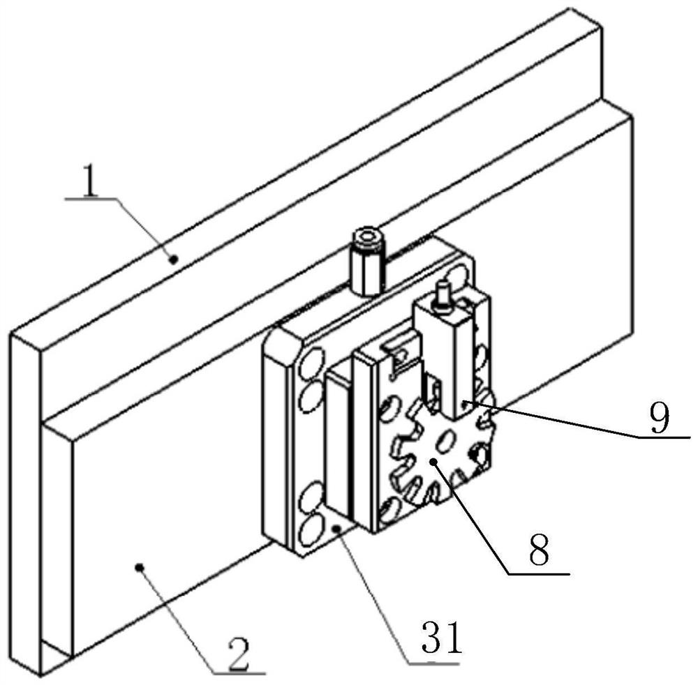
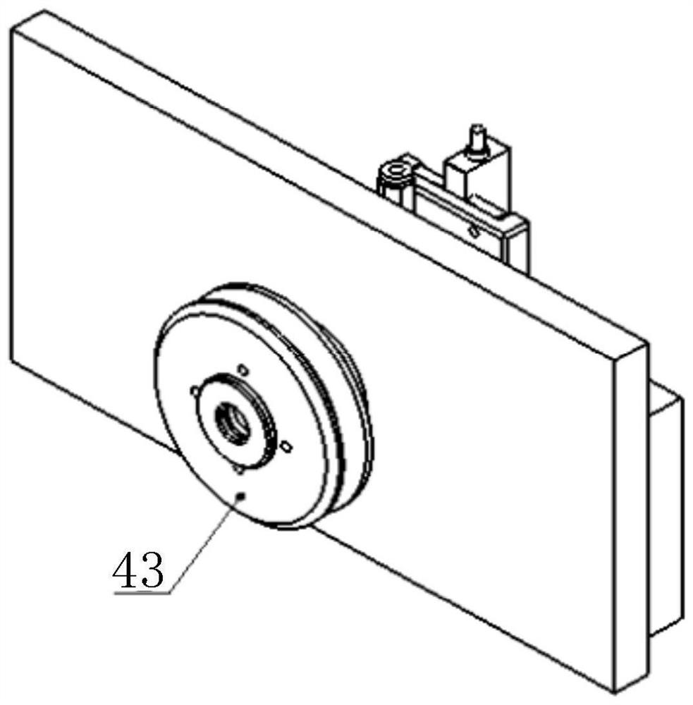
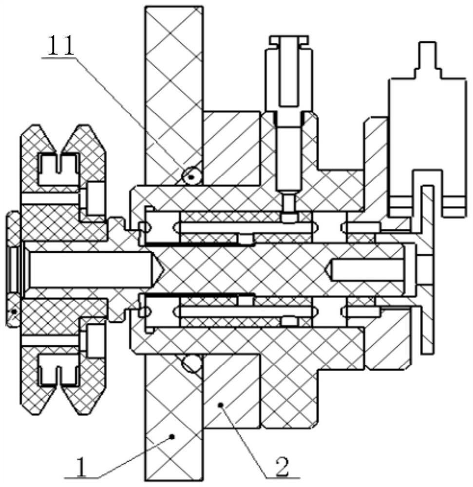
The present application relates to the field of wafer cleaning equipment, in particular to a wafer rotational speed detection device. The wafer rotation speed detection device includes a seating cylinder and a driven shaft. An end cover of one end of the seating cylinder is provided with a mounting hole, and the driven shaft extends into the seating cylinder through the mounting hole, and passes through the first bearing. and the second bearing is rotatably connected with the seat cylinder. An air inlet is formed on the seat cylinder between the first bearing and the second bearing, a first flow channel is formed on the side wall of the driven shaft, and one end of the first flow channel is located between the first bearing and the second bearing, The other end of the first flow channel extends to the side wall of the driven shaft opposite to the inner wall of the installation hole of the seat cylinder, so that the gas entering the seat cylinder can flow to the installation hole through the first flow channel, and then the gas It is introduced into the brushing box through the gap between the installation hole and the driven shaft, so that the gas can play a barrier effect and prevent the cleaning liquid in the brushing box from leaking through the inner cavity of the seat cylinder.

Description

technical field [0001] The present application relates to the field of wafer cleaning equipment, in particular to a wafer rotational speed detection device. Background technique [0002] During the cleaning process of the wafer, the rotational speed of the wafer needs to be measured. Usually, a speed measuring device is set on the wafer scrubbing box. The speed measuring device is installed on the box plate of the scrubbing box through the seat cylinder. It is rotatably connected with the seat cylinder through a bearing, and the driven shaft assists the rotation of the bearing wafer through the driven wheel, and relies on the rotation of the wafer to realize the follow-up rotation, and the rotation speed of the wafer can be obtained by measuring the rotation speed of the driven shaft. Since the seat cylinder and one end of the driven shaft are both located in the brushing box, in order to prevent the cleaning fluid in the brushing box from leaking through the inner cavity of...

Claims


Application Information

Patent Timeline
Patent Type & Authority Patents(China)
IPC IPC(8): G01P3/36H01L21/67
CPCG01P3/36H01L21/6704
Inventor 陶利权于高洋宋文超刘盈楹王丽江胡天水刘凯文郭育澎闫芸
Owner BEIJING SEMICON EQUIP INST THE 45TH RES INST OF CETC
Learn More