Microfluidic flow velocity detection device based on conductive characteristic change

A technology of conductive characteristics and detection devices, which is applied in the field of microfluidic flow rate detection devices based on changes in conductive characteristics, can solve problems such as low precision, and achieve the effect of high flow rate detection accuracy

Inactive Publication Date: 2021-02-09
西安柯莱特信息科技有限公司
View PDF0 Cites 0 Cited by
  • Summary
  • Abstract
  • Description
  • Claims
  • Application Information

AI Technical Summary

Problems solved by technology

Traditional flow rate detection technology based on heat transfer and cantilever beam deformation has low accuracy

Method used


Image

  • Microfluidic flow velocity detection device based on conductive characteristic change
  • Microfluidic flow velocity detection device based on conductive characteristic change

Examples


Embodiment 1

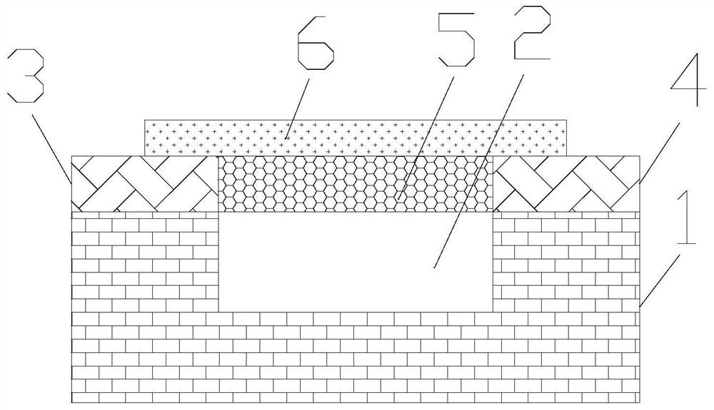
[0020] The invention provides a microfluidic flow velocity detection device based on the change of conductivity characteristics. Such as figure 1 As shown, the microfluidic flow rate detection device based on the change of conductive characteristics includes a microfluidic chip 1 , a first metal part 3 , a second metal part 4 , a first conductive part 5 , and a flexible layer 6 . A fluid channel 2 is provided on the surface of the microfluidic chip 1 . The first metal part 3 and the second metal part 4 are arranged on both sides of the fluid channel 2 respectively, and the material of the first metal part 3 and the second metal part 4 is gold. The first conductive part 5 is fixed between the first metal part 3 and the second metal part 4 . The first conductive part 5 is a rectangle, and the long side of the rectangle is along the connecting line direction between the first metal part 3 and the second metal part 4 . That is to say, the first conductive part 5 is similar to a...

Embodiment 2

[0023] On the basis of Embodiment 1, the first conductive part 5 and the flexible layer 6 are fixedly connected. In this way, driven by the flexible layer 6, the deformation of the first conductive part 5 is more, and the stress in the first conductive part 5 changes more, so the conductive characteristics of the first conductive part 5 change more, thereby realizing more High-precision flow rate detection.

Embodiment 3

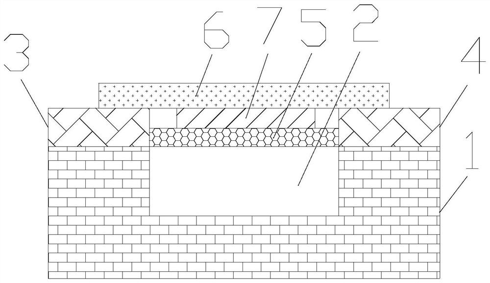
[0025] On the basis of Example 1, such as figure 2 As shown, a second conductive part 7 is also included, and the second conductive part 7 is fixed on the side of the fluid channel 2 of the flexible layer 6 . That is, if figure 2 As shown, the second conductive part 7 is fixed on the lower side of the flexible layer 6 . The material of the second conductive portion 7 is a semiconductor material. The second conductive part 7 is in contact with the first conductive part 5 . A heterojunction is formed between the first conductive portion 5 and the second conductive portion 7 . Under the action of the fluid, when the flexible layer 6 bends outward, the second conductive part 7 and the first conductive part 5 are gradually separated. Because the heterojunction seriously affects the conductive properties of graphene, this embodiment has the advantage of high detection accuracy of flow velocity.

[0026] Furthermore, the semiconductor material is graphene. In this way, a homo...


PUM


Abstract

The invention provides a microfluidic flow velocity detection device based on conductive characteristic change. The microfluidic flow velocity detection device comprises a microfluidic chip, a first metal part, a second metal part, a first conductive part and a flexible layer, wherein the surface of the microfluidic chip is provided with a fluid channel, the first metal part and the second metal part are respectively arranged at two sides of the fluid channel, the first conductive part is fixed between the first metal part and the second metal part, the first conductive part is rectangular, the long edge of the rectangle is in the connecting line direction of the first metal part and the second metal part, the flexible layer is arranged on the micro-fluidic chip, the first metal part and the second metal part, and the fluid channel and the first conductive part are coated with the flexible layer; and the flexible layer is provided with openings at the inlet and the outlet of the fluidchannel respectively. The method has the advantage of high flow velocity detection precision.

Description

technical field [0001] The invention relates to the field of microfluidic flow velocity detection, in particular to a microfluidic flow velocity detection device based on changes in electrical conductivity. Background technique [0002] Microfluidic technology is an important platform for scientific research in the fields of fluid physics, biolaser technology, and microreactors. Microfluidic velocity detection is an important part of microfluidic technology. Traditional flow velocity detection techniques based on heat transfer and cantilever beam deformation have low accuracy. Contents of the invention [0003] In order to solve the above problems, the present invention provides a microfluidic flow rate detection device based on changes in electrical conductivity, including: a microfluidic chip, a first metal part, a second metal part, a first conductive part, a flexible layer, a microfluidic The surface of the control chip is provided with a fluid channel, the first met...

Claims


Application Information

Patent Timeline
Patent Type & Authority Applications(China)
IPC IPC(8): G01P5/08B01L3/00
CPCB01L3/502746G01P5/08
Inventor 不公告发明人
Owner 西安柯莱特信息科技有限公司
Why Eureka
Try Eureka