Microfluidic flow velocity detection device based on magnetic principle

A detection device and microfluidic technology, applied in measurement devices, fluid velocity measurement, fluid controllers, etc., can solve problems such as low accuracy, and achieve the effect of high velocity detection accuracy

Inactive Publication Date: 2021-02-12
西安柯莱特信息科技有限公司
View PDF0 Cites 0 Cited by
  • Summary
  • Abstract
  • Description
  • Claims
  • Application Information

AI Technical Summary

Problems solved by technology

Traditional flow rate detection technology based on heat transfer and cantilever beam deformation has low accuracy

Method used


Image

  • Microfluidic flow velocity detection device based on magnetic principle
  • Microfluidic flow velocity detection device based on magnetic principle
  • Microfluidic flow velocity detection device based on magnetic principle

Examples


Embodiment 1

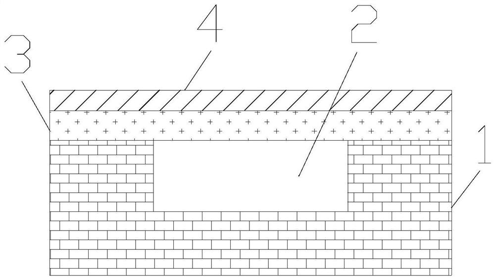
[0021] The invention provides a microfluidic flow velocity detection device based on the magnetic principle. like figure 1 As shown, the microfluidic flow rate detection device based on magnetic principles includes a microfluidic chip 1 , a flexible layer 3 , and a magnetic material part 4 . A fluid channel 2 is provided on the surface of the microfluidic chip 1 . The flexible layer 3 covers the fluid channel 2 , and the flexible layer 3 is respectively provided with openings at the inlet and outlet of the fluid channel 2 . The material of the flexible layer 3 is polydimethylsiloxane. The surface tension of polydimethylsiloxane is small, and under the action of fluid, polydimethylsiloxane can bend outwards more. In addition, polydimethylsiloxane has good chemical stability and is suitable for a wider variety of fluids. The magnetic material part 4 is strip-shaped, the magnetic material part 4 is placed on the flexible layer 3 , and the magnetic material part 4 straddles th...

Embodiment 2

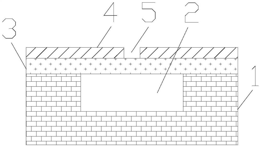
[0024] On the basis of Example 1, such as figure 2 As shown, a gap 5 is provided in the magnetic material portion 4 . The slit 5 is placed in the middle of the fluid channel 2 on the flexible layer 3 . Preferably, the width of the gap 5 is less than 10 microns. More preferably, the width of the gap 5 is close to zero. In this way, under the action of the fluid, when the flexible layer 3 bends outward, the width of the gap 5 increases, seriously increasing the reluctance of the magnetic material part 4, thereby improving the accuracy of flow velocity detection. When the slit 5 is placed in the middle of the fluid channel 2 on the flexible layer 3, under the action of the fluid, the width of the slit 5 increases the most, thereby changing the reluctance of the magnetic material part 4 the most, thereby further improving the flow rate detection. accuracy.

Embodiment 3

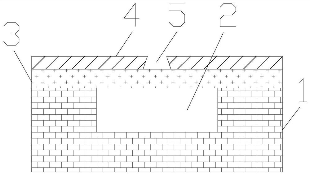
[0026] On the basis of Example 2, such as image 3 As shown, the cross section of the slot 5 is trapezoidal. On the side of the flexible layer 3 , the bottom of the trapezoid is long; on the side away from the flexible layer 3 , the bottom of the trapezoid is short. That is, in image 3 Among them, the lower base of the trapezoid is long; the upper base of the trapezoid is short. Within the gap 5, the magnetic field lines are concentrated near the short sides of the trapezoid. When the flexible layer 3 bends outward under the action of the fluid, the distance between the short sides of the trapezoid changes more, resulting in more changes in the reluctance between the two ends of the magnetic material part 4, thereby improving the accuracy of flow velocity detection.


PUM


Abstract

The invention provides a microfluidic flow velocity detection device based on a magnetic principle. The device comprises a microfluidic chip, a flexible layer and a magnetic material part, the surfaceof the microfluidic chip is provided with a fluid channel, the flexible layer covers the fluid channel, the flexible layer is respectively provided with openings at the inlet and the outlet of the fluid channel, the magnetic material part is strip-shaped, the magnetic material part is arranged on the flexible layer and stretches across the fluid channel. During application, the two ends of the magnetic material part are connected with an outer magnetic circuit to measure the magnetic resistance of the magnetic material part, and flow velocity detection is realized by measuring the magnetic resistance change of the magnetic material part. The device has the advantage of high flow velocity detection precision.

Description

technical field [0001] The invention relates to the field of microfluidic flow velocity detection, in particular to a microfluidic flow velocity detection device based on the magnetic principle. Background technique [0002] Microfluidic technology is an important platform for scientific research in the fields of fluid physics, biolaser technology, and microreactors. Microfluidic velocity detection is an important part of microfluidic technology. Traditional flow velocity detection techniques based on heat transfer and cantilever beam deformation have low accuracy. Contents of the invention [0003] In order to solve the above problems, the present invention provides a microfluidic flow rate detection device based on magnetic principles, which includes a microfluidic chip, a flexible layer, and a magnetic material part. The surface of the microfluidic chip is provided with a fluid channel, and the flexible layer covers Covering the fluid channel, the flexible layer is re...

Claims


Application Information

Patent Timeline
Patent Type & Authority Applications(China)
IPC IPC(8): G01P5/00B01L3/00
CPCB01L3/502746B01L2200/027B01L2400/043G01P5/00
Inventor 不公告发明人
Owner 西安柯莱特信息科技有限公司
Why Eureka
Try Eureka