Flow velocity detection device based on optical fiber deformation
A detection device and optical fiber deformation technology, which is applied in the field of flow velocity detection, can solve the problems of low detection accuracy and achieve the effect of high flow velocity detection accuracy
- Summary
- Abstract
- Description
- Claims
- Application Information
AI Technical Summary
Problems solved by technology
Method used
Image

Examples
Embodiment 1
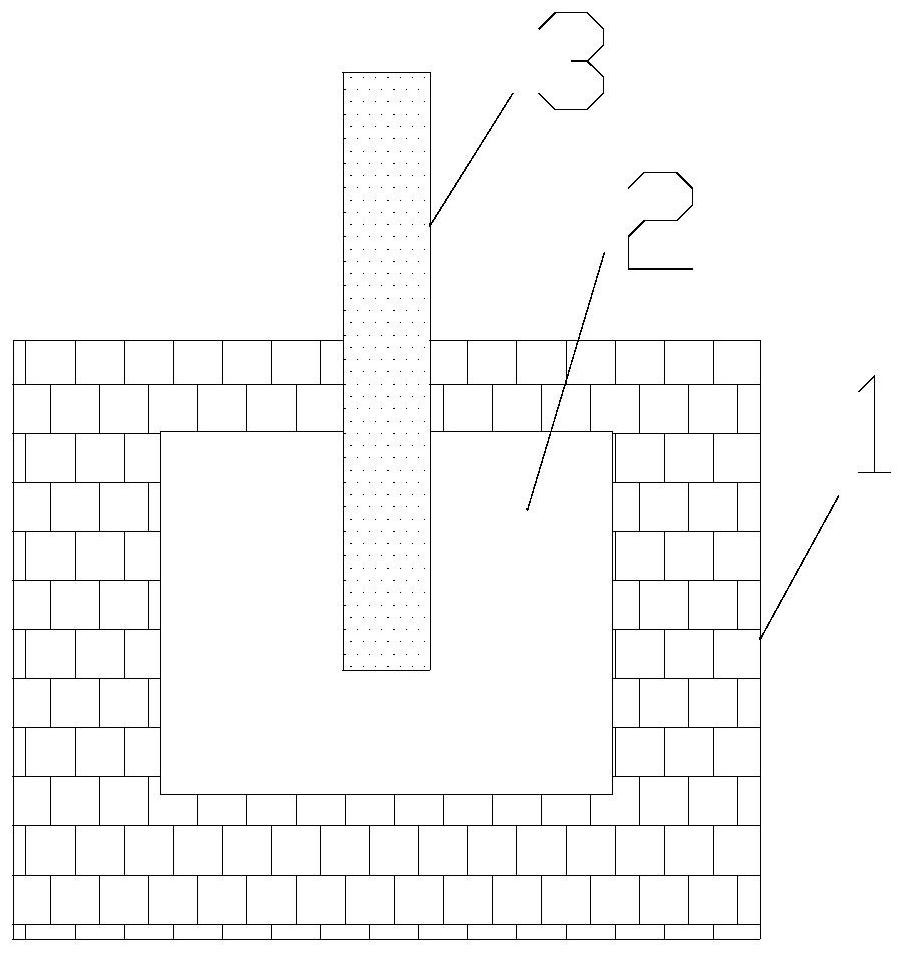
[0021] The invention provides a flow velocity detection device based on optical fiber deformation. Such as figure 1 As shown, the flow velocity detection device based on optical fiber deformation includes a cavity 1 and a micro-nano optical fiber 3 . The cavity 1 encloses a pipe 2 in which fluid flows. The cavity 1 is provided with a through hole through which the micro-nano optical fiber 3 passes, and the end of the micro-nano optical fiber 3 is placed in the pipe 2 . The micro-nano optical fiber 3 is not fixedly connected to the wall of the through hole.
[0022] In application, the light source emits laser light, and the laser light is coupled into the micro-nano fiber 3 ; the light detector detects the laser light reflected from the micro-nano fiber 3 . The laser can be a monochromatic laser or a continuous spectrum laser. When the laser is a monochromatic laser, the photodetector detects the reflection coefficient of the monochromatic laser; when the laser is a contin...
Embodiment 2
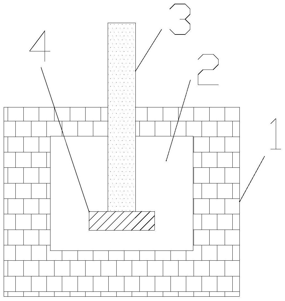
[0026] On the basis of Example 1, such as figure 2 As shown, it also includes a strengthening part 4, the strengthening part 4 is fixed on the end face of the micro-nano fiber 3 in the pipeline, and the strengthening part 4 strengthens the effect of the fluid and the micro-nano fiber 3, so that the micro-nano fiber 3 produces a greater degree The bending of the micro-nano optical fiber 3 can change the reflection characteristics of the micro-nano fiber 3 more, so as to realize the measurement of flow velocity with higher precision. The width of the strengthening part 4 is larger than the diameter of the micro-nano fiber 3 to further enhance the interaction between the fluid and the micro-nano fiber 3 , so that the micro-nano fiber 3 can be bent more significantly. The material of the reinforcing action part 4 is a noble metal, and the noble metal is gold or silver, so as to enhance the reflection effect of the micro-nano fiber 3 end to the incident light, thereby changing the...
Embodiment 3
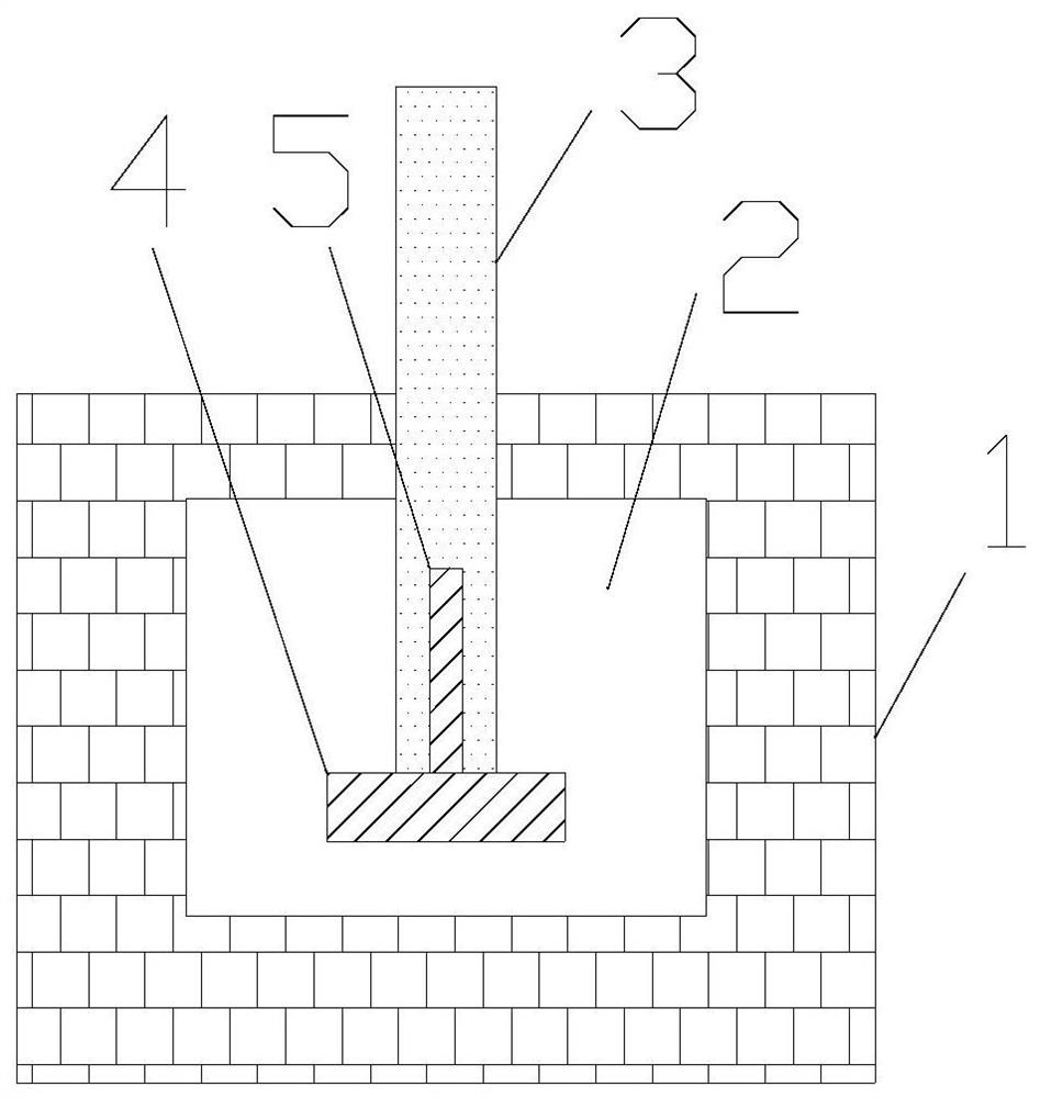
[0028] On the basis of Example 2, such as image 3 As shown, in the duct, the end of the micro-nano fiber 3 only includes the core. On the one hand, the bare core facilitates the coupling of light in the micro-nano fiber 3 with the outside world; on the other hand, the bare core reduces the size of the micro-nano fiber 3, thereby enabling greater bending. The noble metal part 5 is fixed on the fiber core, and the material of the noble metal part 5 is gold. The noble metal part 5 is strip-shaped, and the direction of the strip is along the axial direction of the fiber core. When the noble metal part 5 is arranged on the fiber core, the energy in the fiber core is mainly concentrated between the fiber core and the noble metal part 5 , forming surface plasmon polaritons. In this way, when the core is bent, the noble metal part 5 is bent accordingly. Since the propagation characteristics of the surface plasmon polaritons are very sensitive to the shape of the noble metal part 5,...
PUM
 Abstract
Description
Claims
Application Information