
Detecting foreign substances in a textile material

A technology for textile materials and impurities, which is applied in the field of equipment for detecting impurities in textile materials, can solve problems such as non-immediate application and complex algorithms

Active Publication Date: 2011-09-07
PREMIER EVOLVICS PVT LTD
View PDF6 Cites 0 Cited by
  • Summary
  • Abstract
  • Description
  • Claims
  • Application Information

AI Technical Summary

Problems solved by technology

However, the final algorithm is complex and too general for immediate application

Method used


Image

  • Detecting foreign substances in a textile material
  • Detecting foreign substances in a textile material
  • Detecting foreign substances in a textile material

Examples


Embodiment Construction

[0048] Detailed description of the preferred embodiment

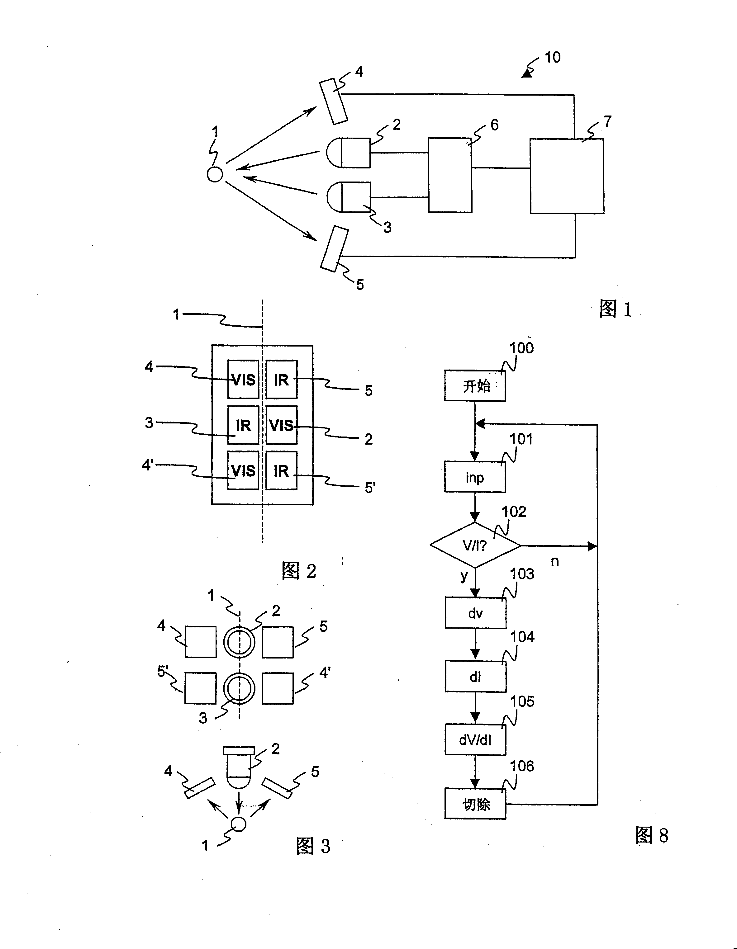
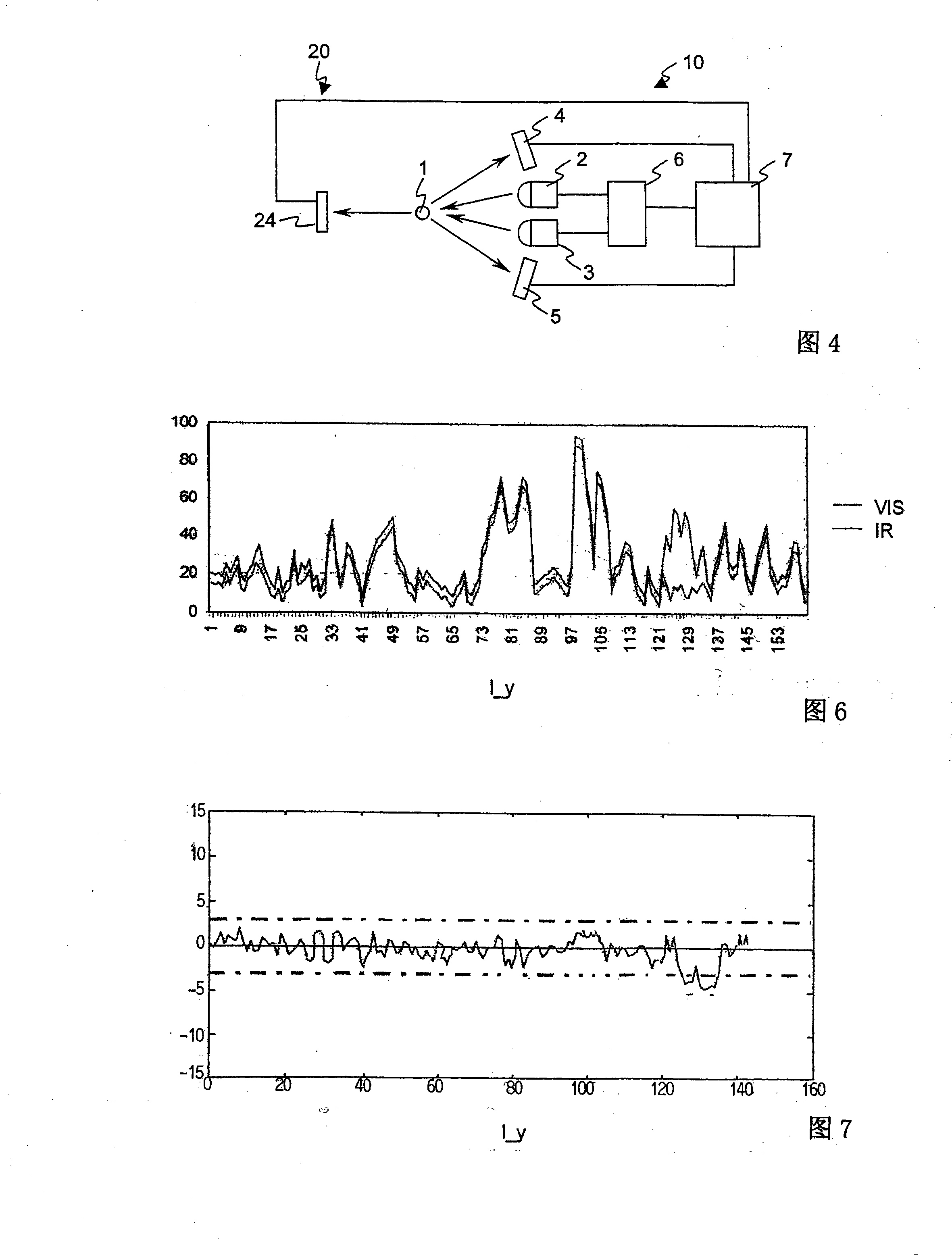
[0049] figure 1 A first test layout is schematically shown, in which the yarn 1 is shown frontally, the first light source 2 and the second light source 3 are arranged to illuminate the same part of the yarn 1, and the first detector 4 and the second detector 5 Arranged to receive light reflected from said portion of yarn 1 . The first light source 2 and the second light source 3 are powered by a drive circuit 6 . The signals from the detector 4 and the first detector 5 are processed by the signal processing section 7 by means of analog or digital signal processing elements. The first detector 4 and the second detector 5 constitute a first detector pair 10 for observing the first side of the yarn 1 .

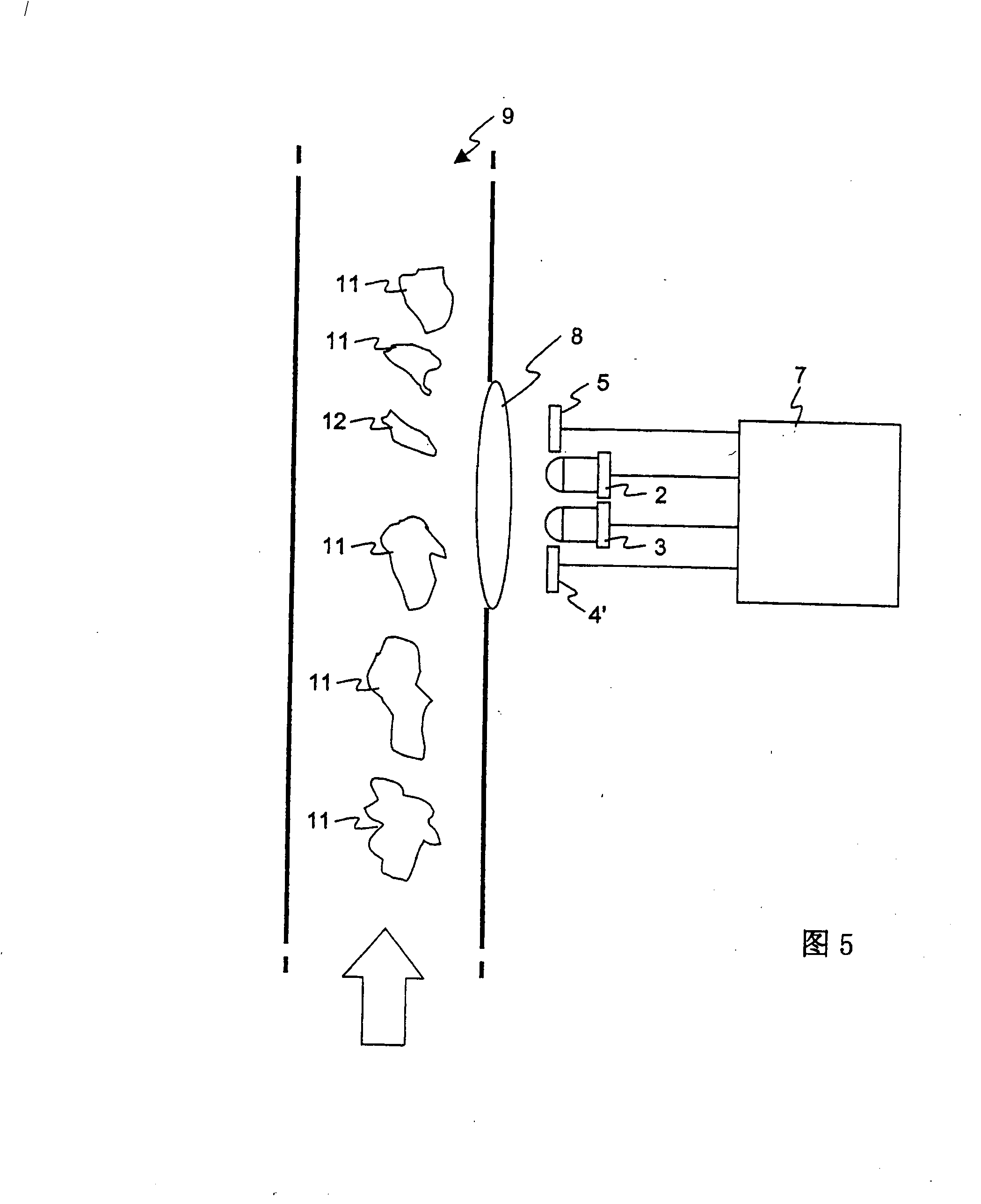
[0050] figure 1 Very simplistic in that it only shows functional relationships between elements, rather than purely geometric relationships. figure 2 The arrangement of light sources and detectors for observing the ya...


PUM


Abstract

An apparatus for detecting foreign substances in a strand-like textile material comprises a first light source (2) for emitting visible light, a second (3) light source for emitting radiation in the infrared spectrum, a first detector (4) sensitive to visible light reflected from a the textile material (1, 11) and configured to generate a corresponding first detector signal, and a second detector(5) sensitive to radiation in the near-visible spectrum reflected from the textile material (1, 11) and configured to generate a corresponding second detector signal. The light sources (2, 3) and detectors (4, 5) are arranged to illuminate and view the same section of the yam (1), and a signal processing section (7) is configured to determine the ratio and a weighted difference of the two detector signals and to output a signal indicative of the presence of a contaminant whenever said difference exceeds a threshold value.

Description

field of invention [0001] The invention relates to a device and method for detecting impurities in textile materials, in particular, the device and method for detecting the presence or absence of contaminants in bundles of textile materials such as yarns, such as in as described in the preambles of the corresponding independent claims. Background of the invention [0002] US 6,175,408 describes a measuring device that emits white light and measures the intensity of light reflected from a moving yarn in the red, green and blue frequency band range. For each of the three possible pairs of intensity signals, a difference signal is formed. Contamination is considered detected when at least one of the difference signals exceeds a given threshold. The key to the invention is the use of a frequency converter that produces white light over a broad spectrum, rather than using a narrow band of a single LED color. [0003] EP 0 399 945 B1 likewise shows a device with a polychromatic...

Claims


Application Information

Patent Timeline
Patent Type & Authority Patents(China)
IPC IPC(8): G01N21/89D01H13/22
CPCD01H13/22G01N33/365G01N21/8915
Inventor S·N·拉马钱德兰纳拉亚纳斯瓦米·卡维塔巴拉苏布拉玛尼姆·沙姆格·桑德拉姆
Owner PREMIER EVOLVICS PVT LTD
Learn More