Optical fiber temperature sensor

An optical fiber temperature and optical fiber sensing technology, applied in thermometers, thermometers with physical/chemical changes, instruments, etc., can solve the problems of low sensitivity, high cost, and high cost of photonic crystal fibers, and achieve high temperature detection sensitivity and low cost. , the effect of simple preparation process

Pending Publication Date: 2022-04-29
陕西咖润特光电科技有限公司
View PDF3 Cites 0 Cited by
  • Summary
  • Abstract
  • Description
  • Claims
  • Application Information

AI Technical Summary

Problems solved by technology

[0006] In the prior art, the cost of fiber grating and photonic crystal fiber is high and the sensitivity is low
Fabrication of fiber optic sensors based on Fabry-Perot interference cavities is complex and costly

Method used


Image

  • Optical fiber temperature sensor
  • Optical fiber temperature sensor
  • Optical fiber temperature sensor

Examples


Embodiment 1

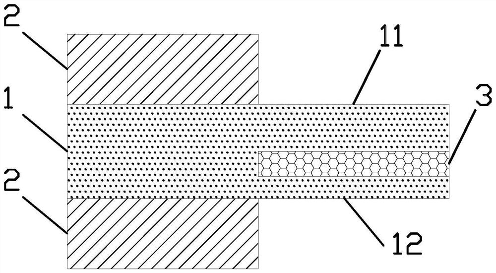
[0026] The invention provides an optical fiber temperature sensor, which includes a light source, a light detector, a circulator, and an optical fiber sensing component. Such as figure 1 As shown, the optical fiber sensing component includes an optical fiber and a thermal expansion material 3 . One end of the optical fiber sensing part is connected to a light source and a light detector through a circulator; at the other end of the optical fiber sensing part, the core 1 protrudes from the cladding 2 . That is to say, at the other end of the optical fiber sensor, the cladding 2 and coating are removed outside the core 1 . In practical applications, only the coating layer can be removed, the key is to reduce the diameter of the optical fiber, making the optical fiber thinner. A slot is provided in the fiber core 1 , and the slot divides the fiber core into a first extension part 11 and a second extension part 12 . The first extension part 11 and the second extension part 12 a...

Embodiment 2

[0031] On the basis of Example 1, such as figure 1 As shown, the lengths of the first extension 11 and the second extension 12 are equal. The lengths of the first extension 11 and the second extension 12 are greater than 1 micron and less than 10 microns, so as to form a resonant cavity in the first extension 11 and the second extension 12 . exist figure 1 On the right side of , when light passes from the core 1 into the first extension 11 and the second extension 12 . Reflection is formed on the right end surfaces of the first extension 11 and the second extension 12 , and resonance is formed in the first extension 11 and the second extension 12 . The width of the slit and the change of the refractive index of PDMS in the slit change the resonant wavelength in the first elongated part 11 and the second elongated part 12 . Temperature detection is realized through the change of the resonant wavelength in the first extension 11 and the second extension 12 . In this embodime...

Embodiment 3

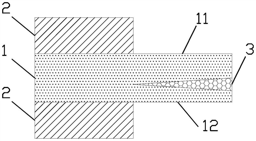
[0033] On the basis of Example 2, such as figure 2 As shown, the thickness of the first extension portion 11 is greater than the thickness of the second extension portion 12 . That is, the first extension 11 is thick, and the second extension 12 is thin. In this way, the resonance wavelength in the first extension 11 is different from the resonance wavelength in the second extension 12 . In the reflection spectrum, there are two reflection resonance wavelengths, and the temperature of the environment to be measured can be determined through the shift of the two resonance wavelengths. Compared with embodiment 2, embodiment 3 has two resonant cavities with different shapes or sizes, which can realize the resonance of two situations, and determine the temperature of the environment to be measured through the resonance of the two situations, which has the advantage of high accuracy of results . In addition, since the thickness of the first extension part 11 and the second exte...


PUM

PropertyMeasurementUnit
Lengthaaaaaaaaaa
Thermal conductivityaaaaaaaaaa
Thicknessaaaaaaaaaa

Abstract

The invention relates to the technical field of temperature measurement, in particular to an optical fiber temperature sensor which comprises a light source, a light detector, a circulator and an optical fiber sensing component, the optical fiber sensing component comprises an optical fiber and a thermal expansion material, one end of the optical fiber sensing component is connected with the light source and the light detector through the circulator, and at the other end of the optical fiber sensing component, a fiber core protrudes out of a wrapping layer. A gap is formed in the fiber core, the fiber core is divided into a first extension part and a second extension part by the gap, and the gap is filled with a thermal expansion material. During application, the device is placed in a to-be-tested environment; light emitted by the light source is transmitted to the composite structure formed by the first extension part, the second extension part and the thermal expansion material along the optical fiber; and temperature detection is realized through the change of the reflected light detected by the light detector. The optical fiber temperature sensor has the advantages of high temperature detection sensitivity, simple process, low cost and the like, and has a good application prospect in the field of optical fiber temperature sensing.

Description

technical field [0001] The invention relates to the technical field of temperature measurement, in particular to an optical fiber temperature sensor. Background technique [0002] Optical fiber temperature sensor has the advantages of small size, fast response speed, anti-electromagnetic interference, etc., so it has been widely concerned. Researchers have developed fiber optic temperature sensors with different structures and working principles, for example, based on fiber Bragg gratings, long-period fiber gratings, Fabry-Perot interference cavities, photonic crystal fibers, etc. [0003] For the temperature sensor of the fiber grating, usually the temperature changes the period of the fiber grating, thereby changing the center wavelength of the fiber grating, and temperature sensing is realized by measuring the movement of the center wavelength, such as the invention patent CN111982169A. [0004] For the temperature sensor of the Fabry-Perot interference cavity, the Fabry...

Claims


Application Information

Patent Timeline
IPC IPC(8): G01K11/32
CPCG01K11/32
Inventor 牛艳娜
Owner 陕西咖润特光电科技有限公司
Why Eureka
Try Eureka