
A Plasma Resonance Sensor Detection System

A plasma resonance and detection system technology, applied in instruments, measuring devices, scientific instruments, etc., can solve the problems of small measurement range, small dielectric constant, low resolution, etc., and achieve the effect of improving detection sensitivity and resolution

Inactive Publication Date: 2019-11-05
SUZHOU UNIV OF SCI & TECH
View PDF1 Cites 0 Cited by
  • Summary
  • Abstract
  • Description
  • Claims
  • Application Information

AI Technical Summary

Problems solved by technology

Due to the small dielectric constant of the prism, the detection system has problems such as low resolution and small measurement range. Therefore, it is necessary to further broaden the measurement range and improve the measurement accuracy.

Method used


Image

  • A Plasma Resonance Sensor Detection System
  • A Plasma Resonance Sensor Detection System
  • A Plasma Resonance Sensor Detection System

Examples


Embodiment 1

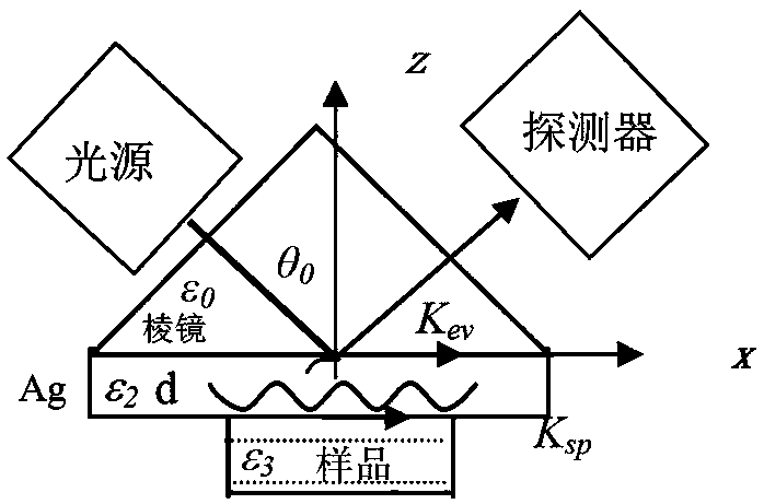
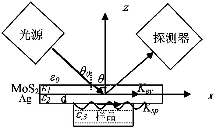
[0020] See attached figure 2 , which is a schematic structural diagram of the molybdenum sulfide-Ag plasmon resonance sensor detection system provided in this embodiment; the detection system includes a light source, a plasmon resonance sensor and a detector. The light source can be a laser, a light emitting diode or an incandescent lamp, etc., and the detector is a photodiode array, a charge-coupled device or a CMOS sensor. Plasmon resonance sensors including MoS 2 Thin film, Ag film and sample box to be tested, wherein the thickness of Ag film is 5-100 nm, MoS 2 The film thickness is 50-100nm. A layer of MoS was prepared on the upper surface of the Ag film 2 film, the sample box to be tested is placed under the silver film.

[0021] in accordance with figure 1 and figure 2 It can be seen from the provided structure comparison that the principle of the present invention is: when the light with wavelength λ is formed by θ 0 The angle is incident on the surface of the ...


PUM

PropertyMeasurementUnit
thicknessaaaaaaaaaa
thicknessaaaaaaaaaa
thicknessaaaaaaaaaa

Abstract

A plasma resonance sensor detection system is disclosed. The system comprises a light source, a plasma resonance sensor and a detector. According to the plasma resonance sensor, a MoS2 film layer the thickness of which is 50-100 nm is prepared on the upper surface of an Ag film the thickness of which is 5-100 nm, and a sample box to be detected is disposed below the Ag film. A metal plasma resonance system comprising the molybdenum sulfide (MoS2) having a high dielectric constant and the silver (Ag) ultrathin film are adopted in a technical scheme, and therefore detection sensitivity and resolution of the SPR sensor can be effectively improved, and a plurality of metal ions such as iron, silver, copper and mercury and organic matters in farmland soil and water can be rapidly and accurately detected.

Description

technical field [0001] The invention relates to a sensor detection device, in particular to a plasma resonance sensor detection system. Background technique [0002] With the discharge of industrial wastewater and the extensive use of chemical fertilizers and pesticides, farmland soil and water resources in some areas have been polluted to varying degrees. Therefore, the development of fast, accurate and easy-to-use sensors, the establishment of a comprehensive monitoring system, and the protection of soil and water safety have become an urgent matter. [0003] In recent years, optical biomonitoring technology has become a rapid detection technology due to the advantages of no need for chemical labels, especially the surface plasmon resonance (Surface Plasmon Resonance, SPR) technology has attracted great attention for its sensitive response, fast and accurate. Surface plasmon resonance is a phenomenon in which light is incident on a metal surface from a medium, and electro...

Claims


Application Information

Patent Timeline
Patent Type & Authority Patents(China)
IPC IPC(8): G01N21/552
CPCG01N21/553
Inventor 马锡英毛红敏
Owner SUZHOU UNIV OF SCI & TECH
Learn More