Micro-fluidic flow velocity detection device based on surface plasmon resonance

A technology of surface plasmon and detection device, which is applied in measurement device, fluid velocity measurement, fluid pressure measurement by optical method, etc., can solve the problem of low precision and achieve the effect of high flow velocity detection

Inactive Publication Date: 2021-02-23
西安柯莱特信息科技有限公司
View PDF0 Cites 0 Cited by
  • Summary
  • Abstract
  • Description
  • Claims
  • Application Information

AI Technical Summary

Problems solved by technology

Traditional flow rate detection technology based on heat transfer and cantilever beam deformation has low accuracy

Method used


Image

  • Micro-fluidic flow velocity detection device based on surface plasmon resonance
  • Micro-fluidic flow velocity detection device based on surface plasmon resonance
  • Micro-fluidic flow velocity detection device based on surface plasmon resonance

Examples


Embodiment 1

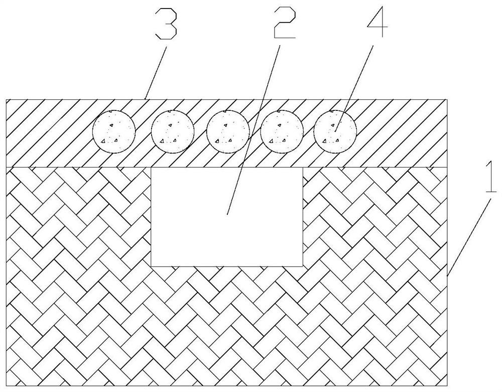
[0021] The invention provides a microfluidic flow velocity detection device based on surface plasmon resonance. Such as figure 1 As shown, the microfluidic flow velocity detection device based on surface plasmon resonance includes a microfluidic chip 1 , a flexible layer 3 , and noble metal particles 4 . The surface of the microfluidic chip 1 is provided with a fluid channel 2, the fluid channel 2 is a groove arranged on the microfluidic chip 1, and the cross section of the groove is rectangular. The flexible layer 3 covers the fluid channel 2 , and the flexible layer 3 is respectively provided with openings at the inlet and outlet of the fluid channel 2 . In this way, only the inlet and outlet of the fluid channel 2 are open, and other parts of the fluid channel 2 are closed. Noble metal particles 4 are arranged in the flexible layer 3 , the material of the noble metal particles 4 is gold or silver, and the size of the noble metal particles 4 is larger than 20 nanometers an...

Embodiment 2

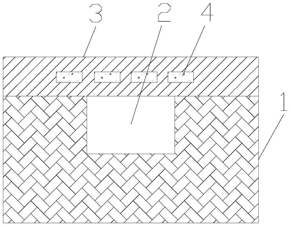
[0024] On the basis of Example 1, such as figure 2 As shown, the noble metal particle 4 is a cuboid, and the long side of the cuboid is perpendicular to the fluid channel 2 . In this way, under the action of the fluid, on the one hand, the distance between the noble metal particles 4 increases; on the other hand, the rectangular parallelepiped noble metal particles 4 are easily elongated. These two effects both cause the surface plasmon resonance wavelength of the noble metal particle 4 to shift, so that the surface plasmon resonance wavelength of the noble metal particle 4 shifts more, thereby achieving higher-precision flow velocity detection.

Embodiment 3

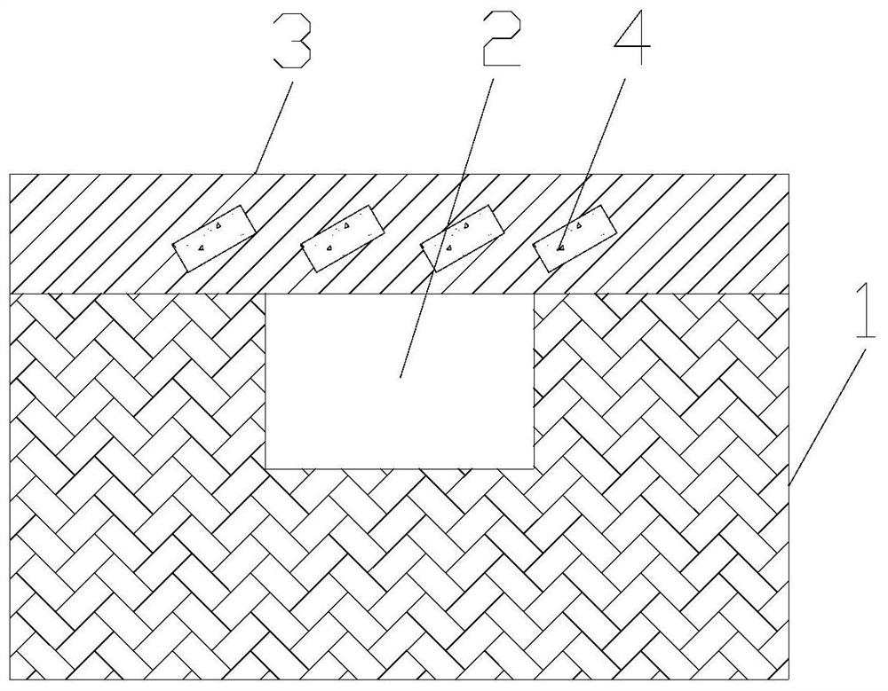
[0026] On the basis of Example 2, such as image 3 As shown, the long side of the cuboid is inclined relative to the normal direction of the flexible layer 3 . That is to say, the included angle between the long side direction of the cuboid and the normal direction of the flexible layer 3 is neither 90 degrees nor 0 degrees. Preferably, the included angle between the long side direction of the cuboid and the normal direction of the flexible layer 3 is greater than 30 degrees and less than 60 degrees. Since the flexible layer 3 covers the fluid channel, the flexible layer 3 in the middle of the fluid channel 2 bends outward more under the action of the fluid; the flexible layer 3 at the edge of the fluid channel 2 bends outward less. In this way, the flexible layer 3 is bent as a whole. When the long side of the cuboid is inclined relative to the normal direction of the flexible layer 3, the bending of the flexible layer 3 will cause more changes in the inclination angle of t...


PUM

PropertyMeasurementUnit
Thicknessaaaaaaaaaa

Abstract

The invention provides a micro-fluidic flow velocity detection device based on surface plasmon resonance, which comprises a micro-fluidic chip, a flexible layer and noble metal particles. The surfaceof the micro-fluidic chip is provided with a fluid channel, the flexible layer covers the fluid channel, the flexible layer is provided with openings at the inlet and the outlet of the fluid channel respectively, the noble metal particles are arranged in the flexible layer, and the flexible layer is made of a transparent material. During application, fluid flows in the fluid channel, the flexiblelayer is bent outwards under pressure, the distance between the noble metal particles is changed, the surface plasmon resonance wavelength of the noble metal particles is changed, and flow velocity detection is achieved by detecting the surface plasmon resonance wavelength of the noble metal particles. The device has the advantage of high flow velocity detection precision.

Description

technical field [0001] The invention relates to the field of microfluidic flow velocity detection, in particular to a microfluidic flow velocity detection device based on surface plasmon resonance. Background technique [0002] Microfluidic technology is an important platform for scientific research in the fields of fluid physics, biolaser technology, and microreactors. Microfluidic velocity detection is an important part of microfluidic technology. Traditional flow velocity detection techniques based on heat transfer and cantilever beam deformation have low accuracy. Contents of the invention [0003] In order to solve the above problems, the present invention provides a microfluidic flow velocity detection device based on surface plasmon resonance, including: a microfluidic chip, a flexible layer, noble metal particles, and a fluid channel is provided on the surface of the microfluidic chip. The flexible layer covers the fluid channel, and the flexible layer is respect...

Claims


Application Information

Patent Timeline
IPC IPC(8): G01P5/02G01L11/02G01B11/16G01N21/552
CPCG01B11/16G01L11/02G01N21/554G01P5/02
Inventor 不公告发明人
Owner 西安柯莱特信息科技有限公司
Why Eureka
Try Eureka