

Microfluidic flow velocity detection device based on light propagation characteristic change
A detection device and microfluidic technology, which is applied in the direction of measuring device, fluid velocity measurement, velocity/acceleration/impact measurement, etc., can solve the problem of low precision and achieve the effect of high accuracy of flow velocity detection
- Summary
- Abstract
- Description
- Claims
- Application Information
AI Technical Summary
Problems solved by technology
Method used
Image

Examples
Embodiment 1
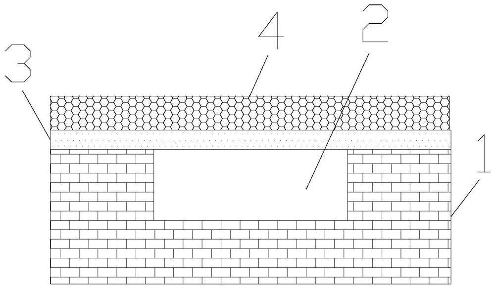
[0021] The invention provides a microfluidic flow velocity detection device based on the change of light propagation characteristics. Such as figure 1 As shown, the microfluidic flow velocity detection device based on the change of light propagation characteristics includes a microfluidic chip 1 , a fiber core 3 , and a flexible layer 4 . A fluid channel 2 is provided on the surface of the microfluidic chip 1, and the cross section of the fluid channel 2 is rectangular. The fiber core 3 is placed on the microfluidic chip 1 , and the fiber core 3 straddles the fluid channel 2 . The fiber core 3 is a micro-nano fiber core, that is to say, the fiber core 3 has a micro-nano size, so as to improve the coupling performance of light in the fiber core 3 and the outside world. The flexible layer 4 covers the fluid channel 2 and the fiber core 3 , and the flexible layer 4 is respectively provided with openings at the inlet and outlet of the fluid channel 2 . On top of the fluid chann...
Embodiment 2
[0026] On the basis of Embodiment 1, the fiber core 3 is in contact with the flexible layer 4 at the top of the fluid channel 2 . That is to say, within the fluid channel 2, the fiber core 3 is only in contact with the flexible layer 4, rather than being connected together. In this way, when the flexible layer 4 bends outward, the flexible layer 4 is separated from the core 3, thereby changing the environment around the core 3, changing the effective refractive index of the environment around the core 3, and changing the core 3 light propagation characteristics. Because the light propagation characteristics of the fiber core 3 , especially the micro-nano fiber core, are very sensitive to its surrounding environment, this embodiment has the advantage of high flow velocity detection accuracy.
Embodiment 3
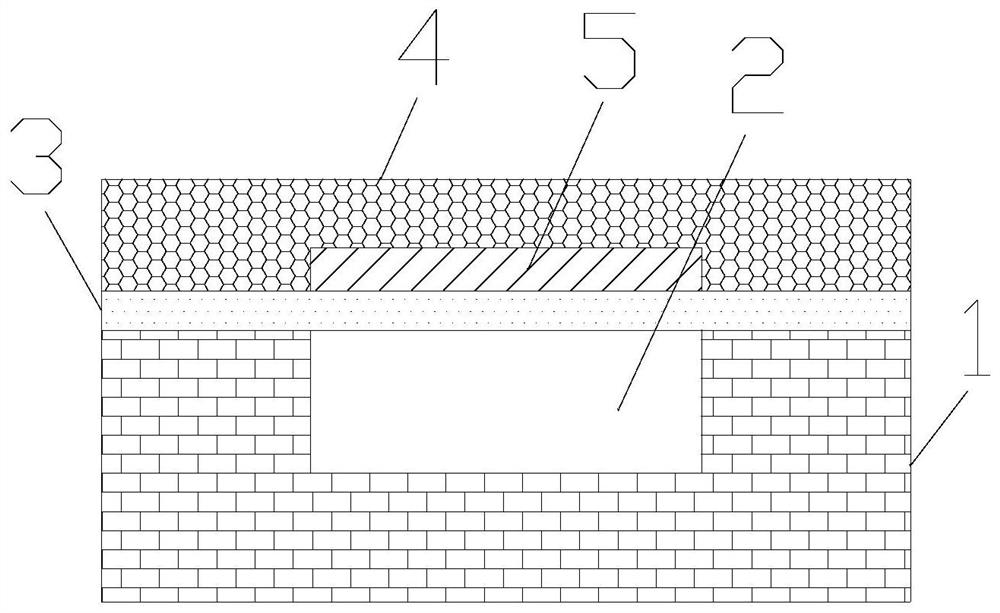
[0028] On the basis of Example 2, such as figure 2 As shown, a noble metal part 5 is also included, and the noble metal part 5 is fixed on the flexible layer 4 in the fluid channel 2 . The noble metal part 5 is strip-shaped, and the strip shape is along the direction of the fiber core 3 , and the noble metal part 5 is in contact with the fiber core 3 . The material of the noble metal portion 5 is gold or silver. When the flexible layer 4 bends outward, the fiber core 3 is separated from the noble metal part 5, thereby changing the coupling between the fiber core 3 and the noble metal part 5, because the coupling performance between the fiber core 3 and the noble metal part 5 is strong, and the fiber core 3 and the noble metal part 5 The change of the spacing between them can more seriously affect the light propagation characteristics of the fiber core 3 , so as to achieve higher-precision flow velocity detection. In addition, the noble metal part 5 is in the shape of a bar....
PUM
 Abstract
Description
Claims
Application Information