Multifunctional teaching electronic instrument cabinet

An electronic instrument and multi-functional technology, applied in the field of multi-functional teaching electronic instrument cabinets, can solve the problems of reducing the functionality of electronic instrument cabinets, reducing the service life and impact of electronic instrument cabinets, so as to improve teaching effects, increase service life, The effect of improving practical performance

Inactive Publication Date: 2021-02-09
浙江华卓机电科技有限公司
View PDF0 Cites 1 Cited by
  • Summary
  • Abstract
  • Description
  • Claims
  • Application Information

AI Technical Summary

Problems solved by technology

The electronic instrument cabinet is one of the commonly used equipment in the modern teaching process. It is used to assist the teaching staff in the classroom teaching work. However, with the continuous popularization of multimedia teaching methods, the shortcomings of the electronic instrument cabinet in the actual use process are urgently needed to be improved. and resolve
[0003] At present, most of the common teaching electronic instrument cabinets on the market are mainly used to assist multimedia teaching work, which cannot be organically combined with traditional teaching methods, and cannot be used directly as a platform, which reduces the functionality of teaching electronic instrument cabinets. In order to facilitate the direct use of teaching staff, most of the operating desks of the electronic instrument cabinets are directly exposed to the air, so that during the long-term use of the electronic instrument cabinets, the dust in the air is likely to affect the display screen and other equipment, reducing the electronic equipment. cabinet lifespan

Method used


Image

  • Multifunctional teaching electronic instrument cabinet
  • Multifunctional teaching electronic instrument cabinet
  • Multifunctional teaching electronic instrument cabinet

Examples


Embodiment Construction

[0026] The following examples are for illustrative purposes only and are not intended to limit the scope of the invention.

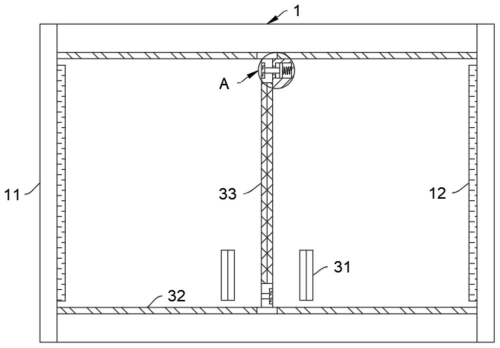
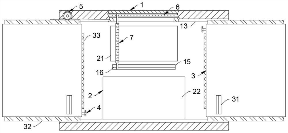
[0027] Such as Figure 1-5 As shown, a multifunctional teaching electronic instrument cabinet includes an instrument cabinet body 1, and an electronic instrument console 2 is arranged on the top of the instrument cabinet body 1. It should be noted that the electronic instrument console 2 includes a display screen 21 and a workbench 22. Both the display screen 21 and the workbench 22 are set in the middle of the instrument cabinet body 1. The display screen 21 slides and cleans through the cleaning plate 7, and the workbench 22 is used for placing equipment such as keyboards and mice. It should be noted that , the specific structure of the instrument cabinet body 1 is the prior art, and has nothing to do with the innovation of the present invention, and the internal component equipment is not limited to the display screen 21 and the workbench 22.

[0028...


PUM


Abstract

The invention belongs to the field of teaching equipment, and particularly relates to a multifunctional teaching electronic instrument cabinet which comprises an instrument cabinet body, an electronicinstrument operation table is arranged at the top of the instrument cabinet body, the instrument cabinet body is slidably connected with cover plates, and the adjacent cover plates are movably connected through buffer pieces. The cover plate and the electronic instrument operation table are arranged in a matched mode, the cover plate is rotationally connected with a screw rod through a transmission mechanism in each opening and closing process, and the screw rod conducts sliding cleaning work on the electronic instrument operation table through a cleaning plate. According to the electronic instrument cabinet, by arranging the cover plate in sliding connection, teaching personnel can flexibly select the teaching mode of the electronic instrument cabinet according to their own teaching modes, the classroom teaching effect is improved, and meanwhile, the electronic instrument cabinet can clean the display screen through the transmission mechanism in the process of sliding the cover plate; and normal use of the display screen is prevented from being influenced by dust and the like, and the service life of the electronic instrument cabinet is prolonged.

Description

technical field [0001] The invention belongs to the field of teaching equipment, in particular to a multifunctional teaching electronic instrument cabinet. Background technique [0002] Multimedia teaching means that in the teaching process, according to the teaching objectives and the characteristics of the teaching objects, through teaching design, rationally select and use modern teaching media, and organically combine with traditional teaching methods, participate in the whole teaching process together, use various media information For students, a reasonable teaching process structure is formed to achieve the optimal teaching effect. The electronic instrument cabinet is one of the commonly used equipment in the modern teaching process. It is used to assist the teaching staff in the classroom teaching work. However, with the continuous popularization of multimedia teaching methods, the shortcomings of the electronic instrument cabinet in the actual use process are urgent...

Claims


Application Information

Patent Timeline
Patent Type & Authority Applications(China)
IPC IPC(8): G09B5/02G09B23/18B08B1/00B08B13/00A47B19/00
CPCA47B19/00B08B1/002B08B1/008B08B13/00G09B5/02G09B23/18
Inventor 朱琪
Owner 浙江华卓机电科技有限公司
Why Eureka
Try Eureka