A grounding structure and connector

A grounding structure and connector technology, which is applied to the connection, the parts of the connecting device, the protective grounding/shielding device of the connecting parts, etc., can solve the problems of poor stability and easy shaking of the contact arm 502, and reduce the probability of shaking, Ensure normal use, improve stability and reliability

Active Publication Date: 2022-08-05
DONGGUAN LUXSHARE TECH CO LTD
View PDF0 Cites 0 Cited by
  • Summary
  • Abstract
  • Description
  • Claims
  • Application Information

AI Technical Summary

Problems solved by technology

Since the other end of the contact arm 502 in contact with the ground terminal is not constrained, the other end of the contact arm 502 is more likely to shake when the connector vibrates, which in turn leads to poor stability of the contact arm 502

Method used


Image

  • A grounding structure and connector
  • A grounding structure and connector
  • A grounding structure and connector

Examples


Embodiment 1

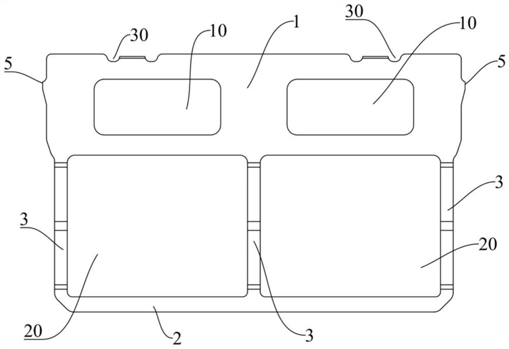
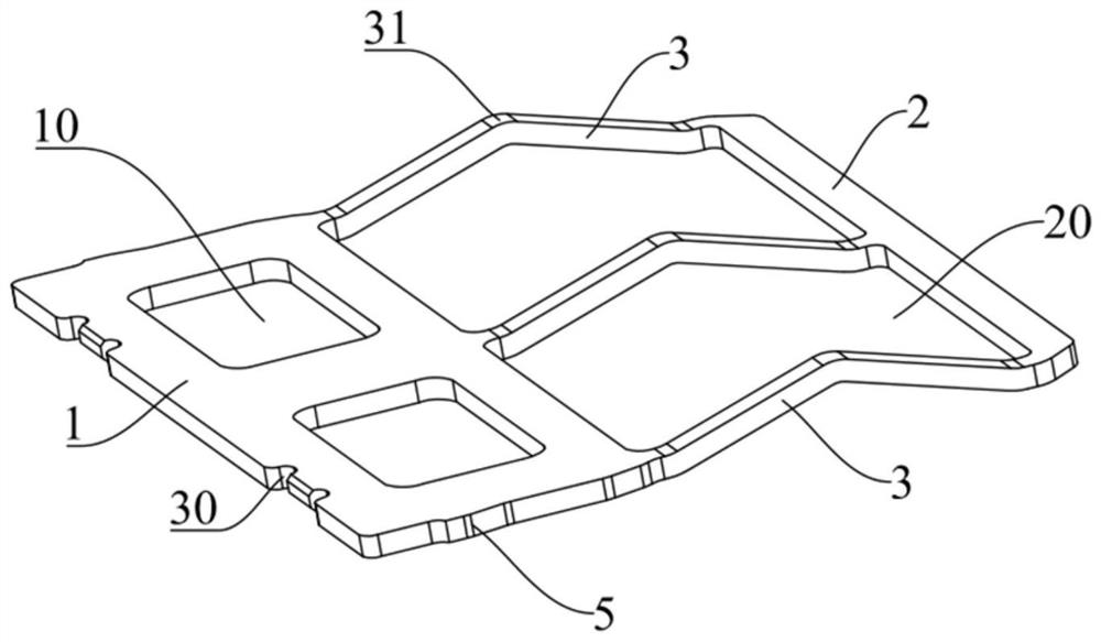
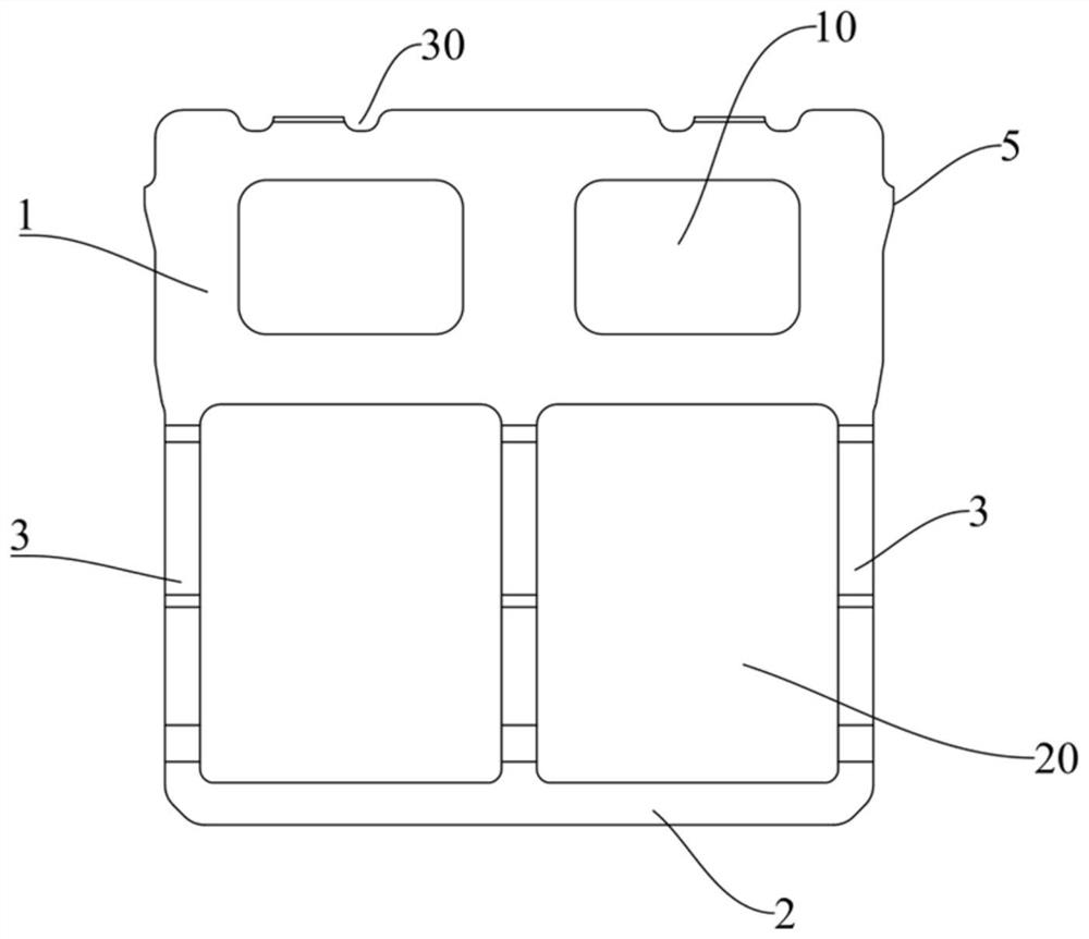
[0062] This embodiment provides a grounding structure, which can improve the stability of the contact arm structure, thereby ensuring the effect of electrical contact between the contact arm structure and the ground terminal.

[0063] like Figure 1 to Figure 7 As shown, the grounding structure includes a first support portion 1 , a second support portion 2 and a contact arm structure 3 , wherein the first support portion 1 and the second support portion 2 are disposed opposite to each other. There are a plurality of contact arm structures 3 , one end of each contact arm structure 3 is fixedly connected to the first support portion 1 , the other end of each contact arm structure 3 is fixedly connected to the second support portion 2 , and the contact arm structure 3 is used to make electrical contact with the ground terminal of the connector.

[0064] In the grounding structure provided in this embodiment, the grounding structure includes a first support portion 1, a second s...

Embodiment 2

[0084] The difference between the grounding structure in the present embodiment and the grounding structure of the first embodiment is that the second support portions 2 are provided on both sides of the first support portion 1 .

[0085] Specifically, as Figure 8 to Figure 12 As shown, there are multiple second support parts 2, one first support part 1, and two opposite sides of the first support part 1 (ie, the first side and the second side of the first support part 1) are provided with For the second support portion 2, the first support portion 1 and each of the second support portions 2 are fixedly connected by the contact arm structures 3, that is, a part of the contact arm structures 3 among the plurality of contact arm structures 3 are located in the first support portion 1, and is fixedly connected with the second support part 2 located on the first side of the first support part 1, and another part of the contact arm structure 3 is located on the second side of the ...

Embodiment 3

[0091] This embodiment also provides a connector, such as Figures 13 to 26 As shown, the connector includes an insulating housing 100, a conductive terminal 200, and the grounding structure 300 in the first and second embodiments above. That is, the connector may only include the grounding structure 300 in the first embodiment, or may It only includes the grounding structure 300 in the second embodiment, and may also include the grounding structure 300 in the first embodiment and the grounding structure 300 in the second embodiment. The insulating housing 100 is provided with an installation slot 101 , the conductive terminal 200 and the grounding structure 300 are arranged in the installation slot 101 , the contact arm structure 3 is in electrical contact with the ground terminal in the conductive terminal 200 , the first support portion 1 and the The two support parts 2 are respectively in contact with the groove walls of the installation groove 101 .

[0092] Further, as ...


PUM


Abstract

The invention discloses a grounding structure and a connector, which belong to the technical field of electrical connectors. The grounding structure includes a first support part; a second support part; and a plurality of contact arm structures. One end is fixedly connected to the first support portion, the other end of each of the contact arm structures is fixedly connected to the second support portion, and the contact arm structures are used for making electrical contact with the ground terminal of the connector. In the grounding structure and the connector provided by the present invention, since the first support part and the second support part have a certain weight and rigidity, when the connector vibrates, the first support part and the second support part can have a small vibration amplitude, Therefore, the contact arm structure has a smaller or even no vibration amplitude, reduces the probability of the contact arm structure shaking, improves the stability of the contact arm structure, and ensures the effect of electrical contact between the contact arm structure and the ground terminal.

Description

technical field [0001] The present invention relates to the technical field of electrical connectors, in particular to a grounding structure and a connector. Background technique [0002] The connector usually includes an insulating housing with an accommodating slot, a conductive terminal and a grounding plate respectively located in the insulating housing, and the conductive terminal includes a plurality of signal terminals and a plurality of grounding terminals, such as Figure 27 As shown, the grounding sheet 501 has a contact arm 502 for making electrical contact with each grounding terminal, and the contacting arm 502 is cantilevered on one end of the grounding sheet 501 . [0003] In the prior art, the contact arm 502 is fixed on one side of the grounding sheet, and one end of the contacting arm 502 is fixedly connected to the grounding sheet, the other end of the contacting arm 502 is an unconstrained free end, and the other end of the contacting arm 502 has a directi...

Claims


Application Information

Patent Timeline
Patent Type & Authority Patents(China)
IPC IPC(8): H01R13/652
CPCH01R13/652H01R13/17H01R12/724H01R13/50H01R13/6471
Inventor 陈宏基
Owner DONGGUAN LUXSHARE TECH CO LTD
Why Eureka
Try Eureka