Supercharge Your Innovation With Domain-Expert AI Agents!

Breast compression and imaging systems and methods

A breast and imaging technology, applied in mammography, tomosynthesis, medical science, etc.

Pending Publication Date: 2021-02-09
HOLOGIC INC
View PDF0 Cites 0 Cited by
  • Summary
  • Abstract
  • Description
  • Claims
  • Application Information

AI Technical Summary

Problems solved by technology

Another known challenge is ensuring that the imaging field includes the desired amount of breast tissue

Method used


Image

  • Breast compression and imaging systems and methods
  • Breast compression and imaging systems and methods
  • Breast compression and imaging systems and methods

Examples


Embodiment Construction

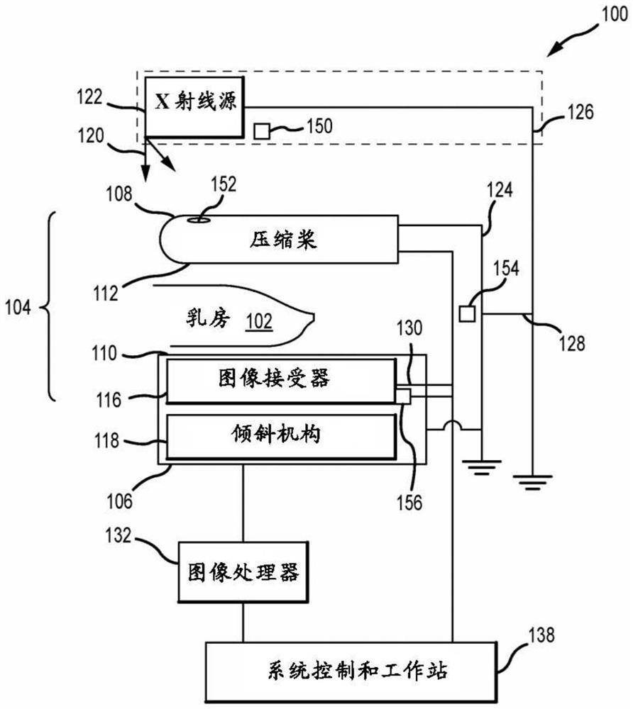
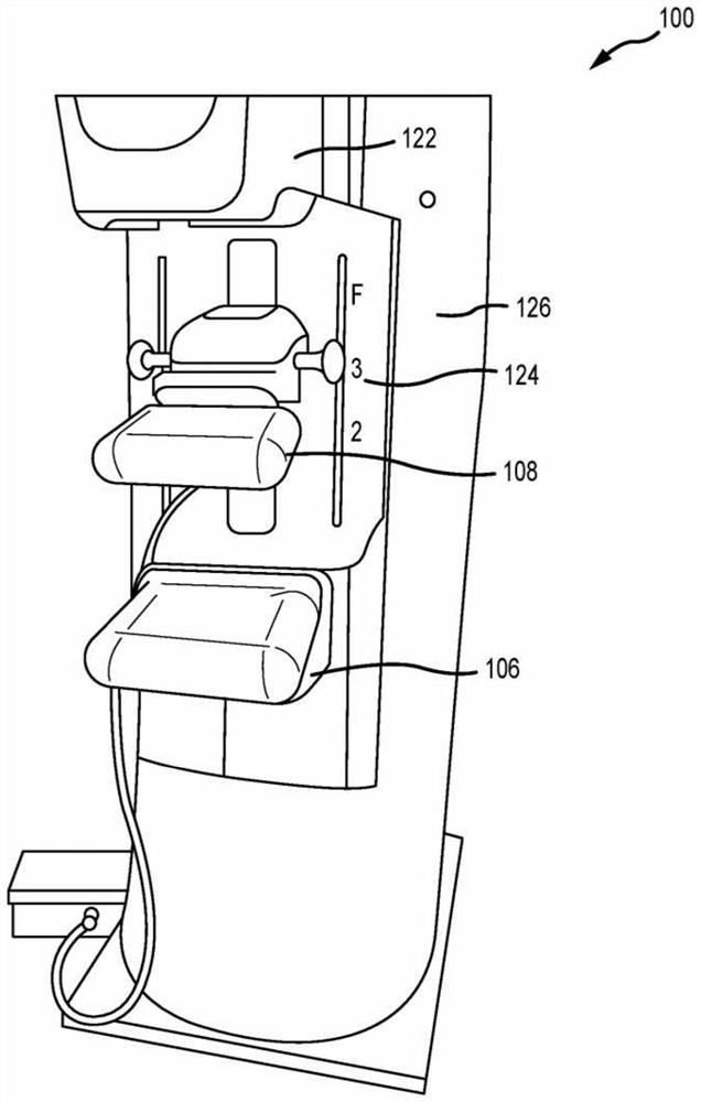
[0021] Figure 1A is a schematic diagram of an exemplary imaging system 100 . Figure 1B is a perspective view of the imaging system 100 . Also refer to Figure 1A and Figure 1B An imaging system 100 immobilizes a patient's breast 102 via a breast compression immobilizer unit or compression system 104 comprising a static breast support platform 106 and movable compression paddles 108 for X-ray imaging (either or both of mammography and tomosynthesis). By). Breast support platform 106 and compression paddle 108 each have compression surfaces 110 and 112 , respectively, that move toward each other to compress and immobilize breast 102 . In known systems, the compression surfaces 110 , 112 are exposed for direct contact with the breast 102 . Platform 106 also houses image receptor 116 and optional tilt mechanism 118 . The holder unit 104 is in the path of an imaging beam 120 emanating from an X-ray source 122 such that the beam 120 impinges on the image receptor 116 .

[00...


PUM


Abstract

A compression paddle with a plurality of markers is advanced towards a patients breast which has been positioned on a support platform for an imaging procedure. An initial position of the compressionpaddle is detected relative to the support platform when a portion of the breast is contacted. An initial marker is identified which is associated with a feature of the breast when the compression paddle is in the initial position. A compression target marker is based at least in part on the initial position and the initial marker.

Description

[0001] Cross References to Related Applications [0002] This application was filed as a PCT International Patent Application on May 22, 2019, and claims priority to U.S. Provisional Patent Application No. 62 / 676,472, filed May 25, 2018, the disclosure of which is incorporated by reference in its entirety This article. Background technique [0003] Compression during mammography and tomosynthesis imaging serves multiple purposes. For example, it: (1) thins the breast in the direction of the X-ray flux, thereby reducing the radiation exposure of the patient from the level required to image the thicker portion of the uncompressed breast; More uniform thickness in the direction of the flux, which facilitates more uniform exposure across the image plane across the breast image; (3) immobilizes the breast during X-ray exposure, thereby reducing image blur; (4) separates breast tissue from the chest wall Bring out into the imaging exposure field, allowing more tissue to be imaged....

Claims


Application Information

Patent Timeline
Patent Type & Authority Applications(China)
IPC IPC(8): A61B6/04A61B6/00
CPCA61B6/0414A61B6/502A61B6/547A61B6/542A61B6/544A61B6/488A61B6/025A61B6/0435A61B6/0492A61B6/461
Inventor S·圣皮埃尔A·雷戈R·G·爱德华兹J·瓦尔托洛内T·韦尔斯
Owner HOLOGIC INC
Features
  • R&D
  • Intellectual Property
  • Life Sciences
  • Materials
  • Tech Scout
  • Unparalleled Data Quality
  • Higher Quality Content
  • 60% Fewer Hallucinations
Learn More