Side drilling device for electronic connector

A technology for electronic connectors and side parts, which is applied in the field of opening devices for side parts of electronic connectors, which can solve the problems of difficult side drilling, inability to adjust the height of electronic connectors, small size of electronic connectors, etc., and achieve the effect of convenient operation

Active Publication Date: 2021-02-12
东台市高科技术创业园有限公司
5 Cites 2 Cited by

AI-Extracted Technical Summary

Problems solved by technology

However, the size of electronic connectors is small, and it is difficult to drill side holes for such parts at present. CNC machine tools can be used for side drilling, but CNC machine tools are expensive, and ordinary manufacturers cannot afford them.
Therefore, if a common drilling machine can be used to drill holes, it will save a lot of cost. The existing method is generally to instal...

Method used

The present invention drives the moving screw rod 43 at both ends of the driving cylinder 41 to move through the rotation of the driving cylinder 41, thereby driving the moving plate 51, the sliding clamping rod 52, the moving column 53, the floating rod 54, the horizontal plate 55, the clamping The plates 6 move laterally together, so that the clamping distance can be adjusted according to electronic conne...

Abstract

The invention discloses a side drilling device for an electronic connector. The side drilling device comprises a base, a telescopic moving mechanism, a clamping plate and a driving mechanism. According to the side drilling device, through rotation of a driving cylinder, moving screw rods at the two ends of the driving cylinder are driven to move, so that a moving plate, a sliding clamping rod, a moving column, floating rods, transverse plates and a clamping plate are driven to transversely move together, and the clamping distance can be adjusted according to electronic connectors with different diameters, and driving screw rods are driven to rotate up and down in positioning threaded cylinders to drive the transverse plates and the floating rods to move up and down, so that the clamping height is changed, the height position of a drilled hole is adjusted, operation is convenient, and double movement adjustment of transverse movement and longitudinal movement can be achieved.

Application Domain

Positioning apparatusMetal-working holders +1

Technology Topic

Drill holeEngineering +3

Image

  • Side drilling device for electronic connector
  • Side drilling device for electronic connector
  • Side drilling device for electronic connector

Examples

  • Experimental program(1)

Example Embodiment

[0019]The content of the present invention will be further described in detail below in conjunction with the accompanying drawings.
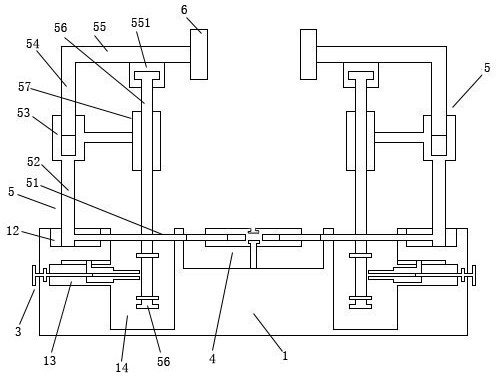
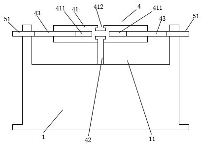
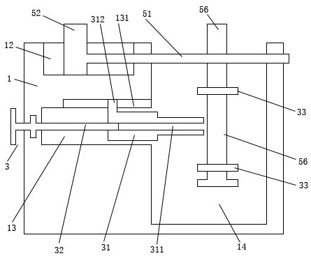
[0020]Such asFigure 1 to 5As shown, a side hole opening device for an electronic connector includes a base 1, a telescopic moving mechanism 5, a clamping plate 6, and a driving mechanism 4. The telescopic moving mechanism 5 includes a moving plate 51, a sliding clamping rod 52, and a moving Column 53, floating rod 54, horizontal plate 55, positioning threaded barrel 57, driving screw 56; a telescopic moving mechanism 5 is installed on both sides of the upper end of the base 1; sliding grooves are respectively provided on both sides of the upper end of the base 1 12; The sliding card slot 12 is respectively slidably clamped to install a sliding clamp rod 52; the inner side of the lower end of the sliding clamp rod 52 is installed with a moving plate 51; the outer end of the moving plate 51 is connected to the sliding clamp Inside the rod 52, the inner end of the moving plate 51 extends from the sliding slot 12 to the middle of the base 1; the upper end of the sliding clamping rod 52 is equipped with a moving column 53; the upper end of the moving column 53 is provided with an insertion groove; A floating rod 54 is slidably sleeved up and down in the insertion slot; a clamping plate 6 is respectively installed on the inner side of the upper end of the floating rod 54 through a horizontal plate 55; a driving screw 56 is respectively installed under the horizontal plate 55 The inner side of the moving column 53 is respectively installed with a positioning threaded barrel 57; the upper end of the drive screw 56 is rotatably clamped and installed below the horizontal plate 55, and the lower end of the drive screw 56 is threaded and rotatably connected to the positioning threaded barrel 57; The mechanism 4 includes a driving cylinder 41, a moving screw 43, and a positioning rod 42; a driving groove 11 is provided in the middle of the upper end of the base 1; a positioning rod 42 is installed at the middle upper end of the driving groove 11; the upper end of the positioning rod 42 rotates Connected to the middle of the side of the driving cylinder 41; the two ends of the driving cylinder 41 are respectively provided with threaded grooves 411; the inner end of the moving plate 51 is respectively installed with a moving screw 43; the threaded grooves at both ends of the driving cylinder 41 411 is threaded to socket a moving screw 43 respectively.
[0021]Such asFigure 1 to 5As shown, in order to realize the linkage locking of lateral movement and longitudinal movement, the present invention further includes a linkage locking mechanism 3; the bottom of the sliding slot 12 is provided with a telescopic groove 13; the inner side of the telescopic groove 13 is respectively provided A locking floating groove 14; the lower end of the driving screw 56 penetrates the moving plate 51 downward and extends into the locking floating groove 14; the linkage locking mechanism 3 includes a telescopic block 31, a rotating screw 32, and an abutting nut 33 The lower ends of the drive screw 56 are threadedly connected with two abutment nuts 33; the telescopic groove 13 is respectively slidably clamped to install a telescopic block 31; the telescopic block 31 is provided with threaded passages 311 penetrating both ends The rotating screw 32 is rotatably clamped on the outer side wall of the telescopic groove 13; the outer end of the rotating screw 32 is located outside the base 1, and the inner end of the rotating screw 32 passes through the thread from the outer end of the telescopic block 31 Through the passage 311; the rotation of the rotating screw 32 drives the telescopic block 31 to move laterally in the telescopic groove 13; the outer end of the telescopic block 31 moves between the abutment nuts 33; the abutment nut 33 rotates It is clamped and installed on the upper and lower sides of the outer end of the telescopic block 31.
[0022]Such asFigure 1 to 5As shown, it is further preferred that a clamping sliding block 312 is provided on the upper end of the outer side of the telescopic block 31; a clamping sliding groove 131 is provided on the inner upper side of the telescopic groove 13; the telescopic block 31 is connected to the sliding block through the upper end 312 is slidably clamped on the clamping sliding groove 131 of the telescopic groove 13. Further, the rotating screw 32 is provided with a rotating snap ring; the outer side wall of the telescopic groove 13 is provided with a rotating snap groove; the rotating screw 32 is rotatably clamped to the outer side wall of the telescopic groove 13 through the rotating snap ring Rotate the card slot. Further, the middle of the side of the driving cylinder 41 is provided with an annular groove 412; the upper end of the positioning rod 42 is provided with arc-shaped clamping teeth; the driving cylinder 41 is rotatably clamped through the circular groove 412 in the middle of the side. On the arc-shaped clamping teeth on the upper end of the positioning rod 42. Further, a positioning block 551 is provided below the horizontal plate 55; a rotary clamping groove is provided on the lower side of the positioning block 551; the upper end of the driving screw 56 is rotatably clamped to the positioning block 551 through a T-shaped clamping tooth Rotate the card slot.
[0023]The present invention drives the moving screw 43 at both ends of the drive barrel 41 to move through the rotation of the drive barrel 41, thereby driving the moving plate 51, the sliding clamping rod 52, the moving column 53, the floating rod 54, the horizontal plate 55, and the clamping plate 6 together. By lateral movement, the clamping distance can be adjusted according to the electronic connectors of different diameters. The driving screw 56 rotates up and down in the positioning screw cylinder 57 to drive the horizontal plate 55 and the floating rod 54 to move up and down, thereby changing the clamping height , Adjusting the height position of the drill hole, convenient operation, the invention can realize the dual movement adjustment of the lateral movement and the longitudinal movement.
[0024]In the present invention, in order to simultaneously position the longitudinal adjustment structure and the lateral adjustment structure, the lower end of the driving screw 56 is penetrated downward on the moving plate 51 and extends into the locking floating groove 14, so that by rotating the screw 32, by rotating The rotation of the screw 32 drives the telescopic block 31 to move from the telescopic groove 13 to the outside. The outer end of the telescopic block 31 is moved between the abutment nuts 33, and the abutment nuts 33 are rotatably clamped and mounted on the outer ends of the telescopic block 31. Side, so that the driving screw 56 is restricted from moving up and down; at the same time, because the lower end of the driving screw 56 penetrates the moving plate 51 downward, the moving plate 56 and the driving screw 51 realize the horizontal synchronous linkage, when abutting the nut 33 When the outer end of the telescopic block 31 is in a clamping and pressing structure, the driving screw 56 realizes lateral positioning, so that the moving plate 51 also realizes lateral positioning, thus realizing the dual limit of longitudinal movement and lateral movement.
[0025]The above descriptions are only preferred embodiments of the present invention and are not intended to limit the present invention. Any modification, equivalent replacement, improvement, etc. made within the spirit and principle of the present invention shall be included in the present invention. Within the scope of protection.

PUM

no PUM

Description & Claims & Application Information

We can also present the details of the Description, Claims and Application information to help users get a comprehensive understanding of the technical details of the patent, such as background art, summary of invention, brief description of drawings, description of embodiments, and other original content. On the other hand, users can also determine the specific scope of protection of the technology through the list of claims; as well as understand the changes in the life cycle of the technology with the presentation of the patent timeline. Login to view more.

Similar technology patents

Graphene film and preparation method therefor

Owner:CHANGZHOU FUXI TECH CO LTD

Driving working load calculation method of automobile driver

InactiveCN101690666AImprove accuracy and timelinessEasy to operate
Owner:BEIJING UNIV OF TECH

Classification and recommendation of technical efficacy words

  • easy to operate

Lancet device

InactiveUS7303573B2inexpensively mass-producedeasy to operate
Owner:ABBOTT DIABETES CARE INC

Rapid and non-invasive optical detection of internal bleeding

InactiveUS20050065436A1easy to operaterapid and accurate result
Owner:HO WINSTON ZONH +2
Why Eureka
Try Eureka