Automatic packaging equipment for frosted sheets
A technology of automatic packaging and frosted sheets, which is applied in the directions of packaging, transportation packaging, transportation and packaging, etc., can solve the problems of slow packaging speed, uniformity, and the degree of uniform packaging cannot be guaranteed, so as to achieve uniform hot-melt packaging and speed up packaging Effect
- Summary
- Abstract
- Description
- Claims
- Application Information
AI Technical Summary
Problems solved by technology
Method used
Image
Examples
Embodiment 1
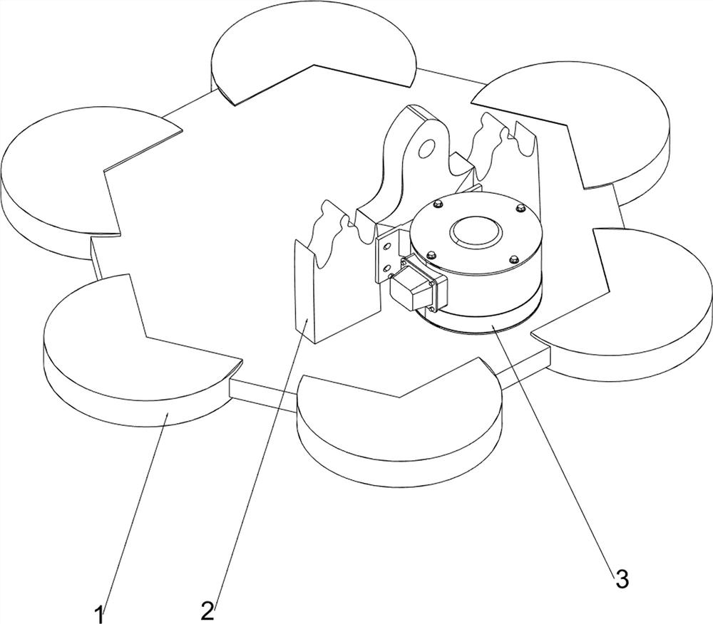
[0023] A frosted sheet automatic packaging equipment, such as figure 1 , figure 2 , image 3 , Figure 4 , Figure 5 As shown, it includes a base plate 1, a support plate 2, a motor 3, a hot-melt mechanism 4 and a rotating mechanism 5, the base plate 1 is provided with a support plate 2, the base plate 1 is provided with a motor 3, and the base plate 1 is provided with a heat-melt mechanism 4 , The bottom plate 1 is provided with a rotating mechanism 5 in a rotating manner.
[0024] First place the matte sheets to be packaged on the rotating mechanism 5, and then turn on the motor 3, the rotation of the output shaft of the motor 3 will drive the operation of the hot-melt mechanism 4, and at the same time drive the operation of the rotating mechanism 5, and then the automatic matte sheet packaging can be realized. Packing, when the packing is finished, turn off the motor 3, the output shaft of the motor 3 stops rotating and the hot-melt mechanism 4 stops working, and the r...
Embodiment 2
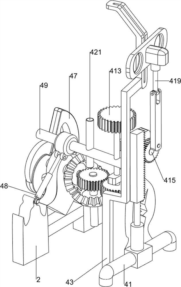
[0026] On the basis of Example 1, such as figure 1 , figure 2 , image 3 , Figure 4 , Figure 5 As shown, the hot-melt mechanism 4 includes a first support frame 41, a second support frame 42, a third support frame 43, a first rotating shaft 44, a first bevel gear set 45, a second rotating shaft 46, a cam 47, a first A contraction rod 48, the first connecting rod 49, fixed round rod 410, full gear set 411, the third rotating shaft 412, the first gear 413, the second contracting rod 414, the second connecting rod 415, the first tooth bar 416, The second gear 417, the third connecting rod 418, the nozzle 419, the fourth connecting rod 420, the ejector rod 421 and the rotating shaft 422; Three rotating shafts 412, the second support frame 42 right side rotating type is provided with the second connecting rod 415, the second connecting rod 415 is provided with the second gear 417, the supporting plate 2 is provided with the second rotating shaft 46 rotatingly, the The secon...
Embodiment 3
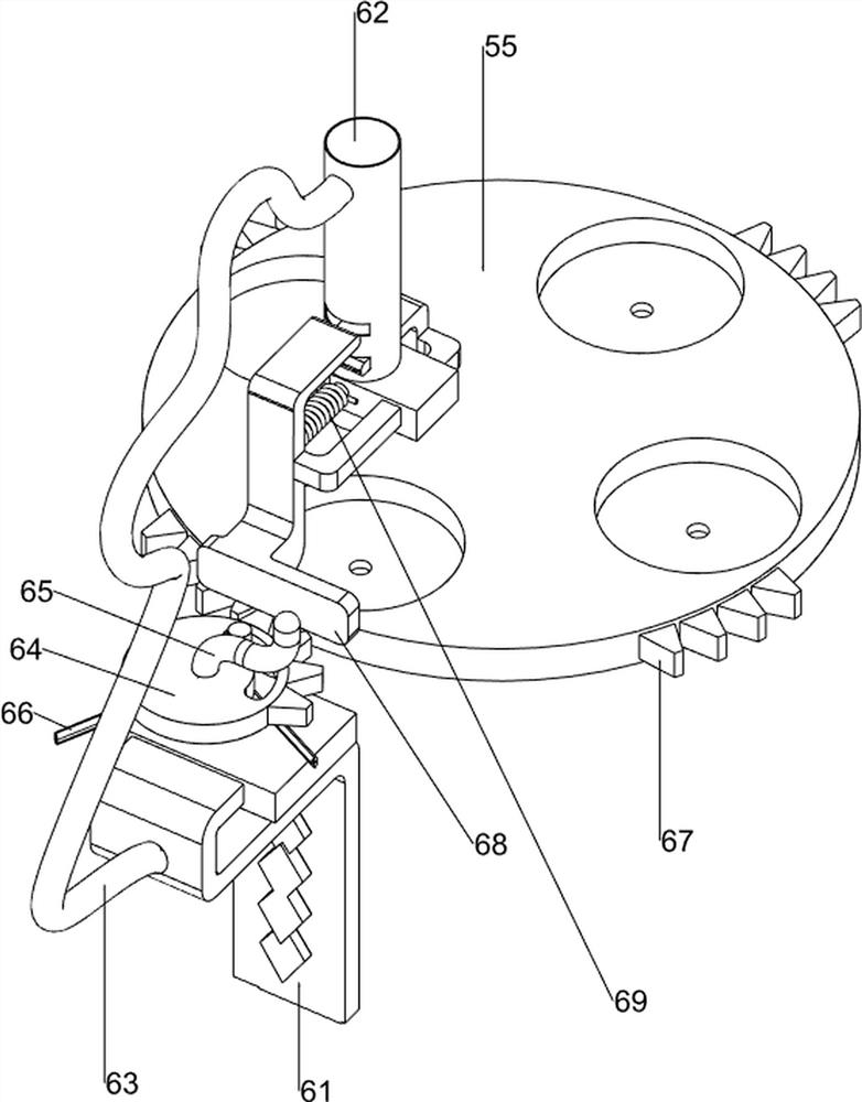
[0031] On the basis of Example 2, such as figure 1 , Figure 6 As shown, it also includes a blanking mechanism 6, the bottom plate 1 is provided with a blanking mechanism 6, and the blanking mechanism 6 includes a fourth support frame 61, a blanking plate 62, a fifth support frame 63, a missing tooth plate 64, a dial Rod 65, torsion spring 66, the second tooth bar 67, push rod 68 and tension spring 69, the left side is provided with the 4th bracing frame 61 on the base plate 1, is provided with the 5th bracing frame 63 on the 4th bracing frame 61, the 4th bracing frame 61 is provided with Five bracing frame 63 is provided with blanking plate 62, and the 4th bracing frame 61 is provided with missing tooth disc 64 in rotation, and missing tooth disc 64 is provided with torsion spring 66, and missing tooth disc 64 is provided with driving lever 65, and The material plate 62 is slidingly provided with a push rod 68, the push rod 68 is provided with a tension spring 69, the right ...
PUM
 Abstract
Description
Claims
Application Information
 - R&D
- Intellectual Property
- Life Sciences
- Materials
- Tech Scout
- Unparalleled Data Quality
- Higher Quality Content
- 60% Fewer Hallucinations
Browse by: Latest US Patents, China's latest patents, Technical Efficacy Thesaurus, Application Domain, Technology Topic, Popular Technical Reports.
© 2025 PatSnap. All rights reserved.Legal|Privacy policy|Modern Slavery Act Transparency Statement|Sitemap|About US| Contact US: help@patsnap.com


