Filling system for coating production

A filling system and coating technology, applied in packaging, bottle filling, liquid bottling, etc., can solve problems affecting filling, splashing of coating liquid, lack of positioning structure, etc., to improve position stability and avoid accidental dumping Effect

Inactive Publication Date: 2021-02-12
安徽子延科技有限公司
View PDF0 Cites 3 Cited by
  • Summary
  • Abstract
  • Description
  • Claims
  • Application Information

AI Technical Summary

Problems solved by technology

[0009] However, there is no positioning structure during filling, and the paint tank is prone to problems such as cheap location or unstable placement, which affects subsequent filling. In addition, during the filling process, the filling head does not move after it moves down to a certain position. Therefore, The distance between the paint liquid level and the filling head is constantly changing, which is easy to cause problems such as splashing of the paint liquid in the paint tank, especially when the paint liquid level is close to the mouth of the paint tank, the paint is easy to splash on the mouth of the tank, affecting the candidate Sealing of paint cans

Method used


Image

  • Filling system for coating production
  • Filling system for coating production
  • Filling system for coating production

Examples


Embodiment 1

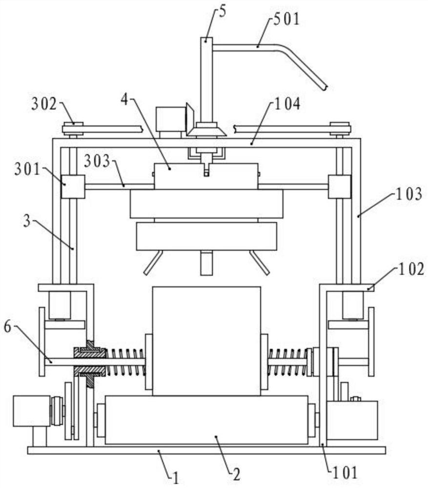
[0050] Please refer to the accompanying drawings, the present invention provides a technical solution: a filling system for paint production, including a base 1, two vertical first side plates 101 are symmetrically fixed on both sides of the top surface of the base 1, the first The top outside of the side plate 101 is fixed with a first horizontal plate 102, the outer end of the first horizontal plate 102 is fixed with a vertical second side plate 103, and a second horizontal plate 103 is fixed between the tops of the two second side plates 103. Horizontal plate 104;

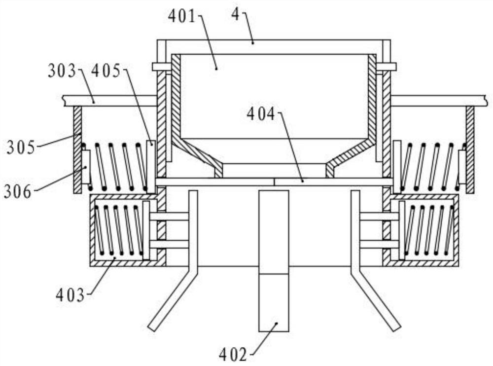
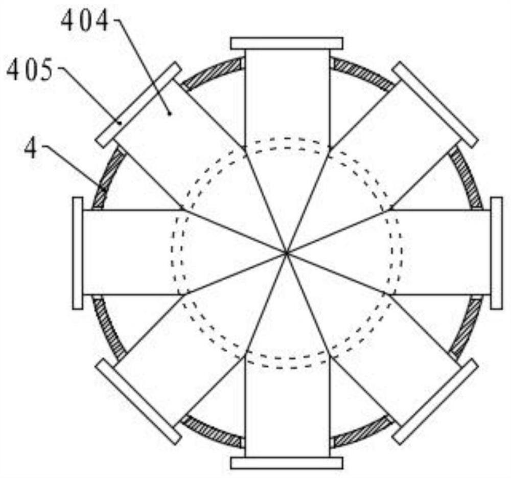
[0051] A conveying assembly is provided between the bottoms of the two first side plates 101, a lifting assembly is provided on the inner side of the second side plate 103, and a lifting cylinder 4 is connected between the two lifting assemblies, and the middle of the second horizontal plate 104 is provided with a lifting assembly. With filling components;

[0052] The conveying assembly includes a conveying be...

Embodiment 2

[0061] The structure of this embodiment is basically the same as that of Embodiment 1, the difference is that the upper part of the first side plate 101 is provided with a positioning assembly 6, and the positioning assembly 6 includes a sliding plate 606 located outside the first side plate 101, the sliding plate 606 Three sliding blocks 607 are fixed along the length direction on the inner surface, and the bottom of the sliding plate 606 is connected with a drive assembly in the middle, and a sliding slot 105 is horizontally arranged in the middle of the first side plate 101. The three sliding blocks 607 are slidably connected in the sliding slot 105 , and the inner side protrudes from the chute 105, and the limiting plate is fixed. The inner side of the sliding block 607 is connected with a positioning plate 601 through a spring. The outer end of the outer end passes through the corresponding sliding block 607 and protrudes, and the extended ends of the three positioning rod...

Embodiment 3

[0067] The structure of this embodiment is basically the same as that of Embodiment 2, the difference is that the second pulley 604 is coaxially fixed on the two rotating disks 605, and a third belt is connected to one side of the second pulley 604 through a transmission link. The drive shaft is fixed at the center of the third pulley, and the drive shafts on both sides rotate with the first side plate 101 on the corresponding side and are coaxially fixed. Through the drive shaft, the second pulley 604 and the third pulley The transmission makes the drive components on both sides move synchronously.


PUM


Abstract

The invention discloses a filling system for paint production in the technical field of paint production. The filling system comprises a base, first side plates, second side plates and a second transverse plate, wherein a conveying assembly is arranged between the first side plates, lifting assemblies are arranged on the second side plates, a lifting cylinder is connected to the second side platesthrough the lifting assemblies, and a filling assembly is arranged on the second transverse plate. According to the filling system, the lifting cylinder is driven by the lifting assemblies to move downwards, so that a filling opening in a material blocking hopper is located in the inner side of an opening of a coating tank, and coating liquid is effectively prevented from accidentally splashing to the opening of the coating tank through the material blocking hopper; pressing plates are tightly pressed on the side wall of the coating tank through springs, so that the position stability of thecoating tank is improved; and a filling pipe moves, a filling head extends into the coating tank to fill coating liquid, the filling head is moved along with rising of the coating liquid level, and acertain distance is kept between the filling head and the liquid level all the time, so that the situation that the filling head extends into the coating liquid or the coating liquid splashes due to the fact that the distance is too long is avoided.

Description

technical field [0001] The invention relates to the technical field of paint production, in particular to a filling system for paint production. Background technique [0002] Paint, traditionally called paint in China. The so-called paint is coated on the surface of the object to be protected or decorated, and can form a continuous film firmly attached to the object to be coated, usually based on resin, oil, or emulsion, with or without adding pigments, fillers, adding The corresponding additives are viscous liquids prepared with organic solvents or water. [0003] The relatively authoritative book "Painting Technology" in the Chinese coatings industry defines it as follows: "Painting is a material that can be coated on the surface of an object by different construction techniques to form a firm adhesion, a certain strength, and a continuous coating. Solid film. The film formed in this way is commonly called a coating film, also known as a paint film or a coating." [000...

Claims


Application Information

Patent Timeline
Patent Type & Authority Applications(China)
IPC IPC(8): B67C3/24B67C3/26B67C3/22
CPCB67C3/22B67C3/24B67C3/26
Inventor 黄彦子
Owner 安徽子延科技有限公司
Why Eureka
Try Eureka