
Method for measuring and adjusting spatial position relationship of multiple positioners

A technology of spatial position and adjustment method, which is applied in the directions of measuring device, surveying and navigation, measuring inclination, etc. It can solve the problems of large external influence factors, influence of attitude adjustment accuracy, and large cumulative error.

Active Publication Date: 2021-02-12
CHENGDU AIRCRAFT INDUSTRY GROUP
View PDF9 Cites 5 Cited by
  • Summary
  • Abstract
  • Description
  • Claims
  • Application Information

AI Technical Summary

Problems solved by technology

[0002] In the field of attitude adjustment and alignment of large components, the attitude adjustment platform is mostly constructed by connecting multiple locators in series and parallel, and multiple locators are linked to complete the adjustment of the component attitude. The spatial relationship between multiple locators directly affects the attitude adjustment. Accuracy, if the accuracy is out of tolerance, the parts will be pulled and squeezed during the attitude adjustment process
For the measurement and adjustment of the spatial position relationship of multiple locators during equipment installation and commissioning, most of the existing technologies use a flat ruler as an intermediate reference method. There are many variables affecting the accuracy, and the cumulative error is large. If the span between locators is large, it is still It is necessary to make extended bridge tooling, and only one movement axis in one direction can be measured and adjusted at a time. The process is cumbersome and the external factors are large

Method used


Image

  • Method for measuring and adjusting spatial position relationship of multiple positioners
  • Method for measuring and adjusting spatial position relationship of multiple positioners
  • Method for measuring and adjusting spatial position relationship of multiple positioners

Examples


Embodiment 1

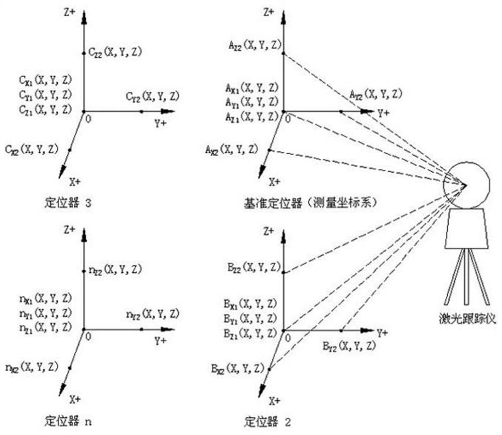
[0044] A method for measuring and adjusting the spatial position relationship of multiple locators in this embodiment, such as figure 1 As shown, step 1. Determine the reference X-axis and reference Y-axis that are perpendicular to each other, and use the reference positioner to level the reference X-axis and reference Y-axis, so that the reference X-Y plane remains horizontal, and establish a plane perpendicular to the reference X-Y plane. The reference Z axis forms the reference coordinate system;

[0045] Step 2. Use the adjusting positioner to measure the adjustment positioning coordinates of the positioner X-axis, positioner Y-axis, and positioner Z-axis respectively in the reference coordinate system, and calculate the positioner X-axis, positioner Y-axis, and positioning coordinates by adjusting the positioning coordinates. The spatial positional relationship between the Z-axis of the device and the reference X-axis, reference Y-axis, and reference Z-axis respectively; ...

Embodiment 2

[0051] This embodiment is further optimized on the basis of Embodiment 1. In the step 2, two points are selected on the X-axis of the positioner, the Y-axis of the positioner, and the Z-axis of the positioner as the positive limit point and the negative limit point respectively. position, and then move the adjusting locator to the positive limit point and the negative limit point respectively to measure the coordinates of the positive limit point and the negative limit point, and obtain the locator through the positive limit coordinates and the negative limit coordinates The space position vector of the X-axis, the Y-axis of the locator, and the Z-axis of the locator.

[0052] Select the positive limit point and the negative limit point on the X-axis of the positioner respectively, and the coordinate of the negative limit measurement point on the X-axis of the positioner is B X1 (X, Y, Z), the positive limit measuring point coordinates of the X axis of the positioner is B X2 ...

Embodiment 3

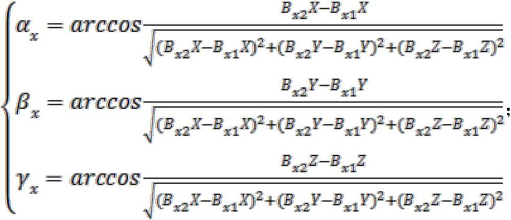
[0057] This embodiment is further optimized on the basis of the above-mentioned embodiment 1 or 2. The spatial position relationship refers to the X-axis of the locator, the Y-axis of the locator, the Z-axis of the locator and the reference X-axis, the reference Y-axis, and the reference Z. The angle relationship between two axes, the calculation formula of the angle relationship is as follows:

[0058] The included angles between the X-axis of the positioner and the reference X-axis, reference Y-axis, and reference Z-axis are:

[0059]

[0060] where: α x is the angle between the X-axis of the positioner and the reference X-axis; β x is the angle between the X-axis of the positioner and the reference Y-axis; γ x is the angle between the X-axis of the positioner and the reference Z-axis; B x1 X is the X coordinate value of the negative limit point of the X axis of the positioner; B x2 X is the X coordinate of the positive limit point of the X axis of the locator; B x1 ...


PUM


Abstract

The invention discloses a method for measuring and adjusting the spatial position relationship of multiple positioners. The method comprises the steps of: respectively measuring the coordinates of a positive limiting point and the coordinates of a negative limiting point on a reference X axis, a reference Y axis and a reference Z axis through a reference positioner, obtaining the spatial positionsof the reference X axis, the reference Y axis and the reference Z axis, and building a reference coordinate system; measuring the coordinates of the positive limiting point and the coordinates of thenegative limiting point on a positioner X-axis, a positioner Y-axis and a positioner Z-axis respectively through an adjustment positioner, and then obtaining the spatial position relations between the positioner X-axis and the reference X-axis, between the positioner Y-axis and the reference Y-axis, and between the positioner Z-axis and the reference Z-axis, and calculating the adjustment amountsbetween the positioner X-axis and the reference X-axis, between the positioner Y-axis and the referenceY-axis, and between the positioner Z-axis and the reference Z-axis respectively, and then accurately, conveniently and quantitatively adjusting the spatial positions of the positioner X-axis, the positioner Y-axis and the positioner Z-axis so as to enable errors among positioners to reach standards.

Description

technical field [0001] The invention belongs to the technical field of equipment space position debugging, and in particular relates to a method for measuring and adjusting the space position relationship of a plurality of locators. Background technique [0002] In the field of attitude adjustment and alignment of large components, the attitude adjustment platform is mostly constructed by connecting multiple locators in series and parallel, and multiple locators are linked to complete the adjustment of the component attitude. The spatial relationship between multiple locators directly affects the attitude adjustment. Accuracy, if the accuracy is out of tolerance, it will cause the parts to be pulled and squeezed during the attitude adjustment process. For the measurement and adjustment of the spatial position relationship of multiple locators during equipment installation and commissioning, most of the existing technologies use a flat ruler as an intermediate reference metho...

Claims


Application Information

Patent Timeline
IPC IPC(8): G01B11/00G01C9/00
CPCG01B11/002G01C9/00
Inventor 欧习阳蔡明李步金李志强黄超
Owner CHENGDU AIRCRAFT INDUSTRY GROUP
Learn More