Device and method for quickly calibrating mechanical tensiometer

A technology of calibration device and calibration method, which is applied in force/torque/power measuring instrument calibration/testing, measuring devices, instruments, etc., can solve problems such as assembly errors cannot be eliminated, assembly efficiency is reduced, overshooting, repetition, etc., to achieve The tension control accuracy is improved, the tension calibration efficiency is improved, and the effect of strong field practicability

Active Publication Date: 2021-02-12
BEIJING SATELLITE MFG FACTORY
View PDF10 Cites 1 Cited by
  • Summary
  • Abstract
  • Description
  • Claims
  • Application Information

AI Technical Summary

Problems solved by technology

[0005]Because the elastic coefficient k of the head spring of each tensiometer cannot be completely consistent, and there is a calibration error when the tensiometer is calibrated, the readings of each tensiometer under the same working condition have inherent difference
The assembly error caused by the inherent difference of the tensiometer cannot be eliminated, so the phenomenon of overshoot and repetition often occurs in each unfolding test process, which seriously reduces the assembly efficiency

Method used


Image

  • Device and method for quickly calibrating mechanical tensiometer
  • Device and method for quickly calibrating mechanical tensiometer
  • Device and method for quickly calibrating mechanical tensiometer

Examples


Embodiment Construction

[0040] The present invention will be further elaborated below in conjunction with embodiment.

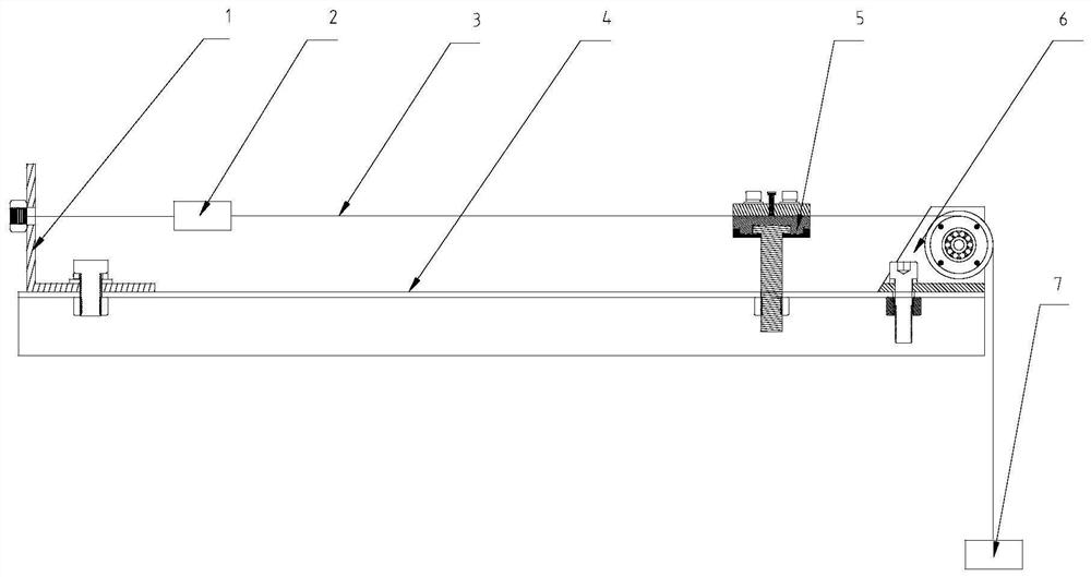
[0041] Such as figure 2 As shown, the present invention provides a quick calibration device for a mechanical tensiometer, which includes a connection assembly 1 , a sensor 2 , a rope 3 to be tested, a groove rail 4 , a fastening assembly 5 , a pulley assembly 6 and a weight 7 .

[0042] The grooved rail 4 is placed horizontally, and the connecting assembly 1 is an L-shaped structure, including a first side plate and a second side plate perpendicular to each other. The first side plate of the connecting assembly 1 is fitted and fixed on one end of the grooved rail 4, and the pulley assembly 6 is fixed on On the other end of the grooved rail 1, the bottom of the fastening assembly 5 is fixed at the middle position of the grooved rail 4, and a square groove is arranged on the top;

[0043] The second side plate of the connection assembly 1 is perpendicular to the groove rail 4, and i...


PUM


Abstract

The invention relates to a device and method for quickly calibrating a mechanical tensiometer. The device comprises a connecting assembly, a sensor, a to-be-measured rope, a grooved rail, a fasteningassembly, a pulley assembly and a weight. The grooved rail is horizontally arranged; the connecting assembly is of an L-shaped structure and comprises a first side plate and a second side plate whichare perpendicular to each other, and the first side plate of the connecting assembly is attached to and fixed to one end of the grooved rail; the pulley assembly is fixed to the other end of the grooved rail; the bottom of the fastening assembly is fixedly located in the middle of the grooved rail; a square groove is formed in the top of the fastening assembly; the second side plate of the connecting assembly is perpendicular to the grooved rail and used for being fixedly connected with one end of the sensor; the other end of the sensor is fixedly connected with a to-be-measured rope; the to-be-measured rope penetrates through the square groove of the fastening assembly and is fastened to the fastening assembly; the to-be-measured rope changes to extend in a vertical direction through thepulley assembly; the weight is fixedly connected to the tail end of the to-be-measured rope; after being installed, the to-be-measured rope is just tangent to the bottom of the square groove of the fastening assembly and the pulley assembly.

Description

technical field [0001] The invention relates to a device for quick calibration of a mechanical tensiometer, in particular to a device for precise tension detection of a rope-like linkage mechanism, and belongs to the technical field of precise assembly of space expandable mechanisms. Background technique [0002] The linkage device widely exists in the space deployable mechanism represented by the solar wing, and is an important part of the solar wing deployment mechanism. The key to normal deployment. [0003] At present, the ropes used for linkage devices mainly include steel wire ropes and Kevlar ropes. According to different space environments, ropes of different materials are suitable. The two ends of the rope are respectively fixed on the linkage wheels of the solar wing hinge and cannot move freely. Due to the high-precision assembly requirements of the solar wing deployment mechanism, it is necessary to strictly control the tension of the rope during the assembly p...

Claims


Application Information

Patent Timeline
Patent Type & Authority Applications(China)
IPC IPC(8): G01L25/00
CPCG01L25/00
Inventor 胡亚航王国星程泽臧梓轶齐向军段萍高明强姚迪薛文娟
Owner BEIJING SATELLITE MFG FACTORY
Why Eureka
Try Eureka