Precision compensation system suitable for chip mounter

A technology of precision compensation and placement machine, which is applied in the direction of assembling printed circuits, electrical components, and electrical components with electrical components. It can solve the problems of angle deflection of electronic components and inaccurate placement accuracy, and achieve the effect of preventing placement errors.

Active Publication Date: 2021-02-12
爱微(江苏)电力电子有限公司
View PDF2 Cites 3 Cited by
  • Summary
  • Abstract
  • Description
  • Claims
  • Application Information

AI Technical Summary

Problems solved by technology

However, there is a problem when the electronic components are mounted on the PCB board. Because the pick-and-place machine picks up the electronic components during the placement process, the angle of the electronic components will deflect when picking up, and it cannot be accurately located in the center of the placement head. , resulting in inaccurate mounting accuracy

Method used


Image

  • Precision compensation system suitable for chip mounter
  • Precision compensation system suitable for chip mounter
  • Precision compensation system suitable for chip mounter

Examples


Embodiment Construction

[0071] The following will clearly and completely describe the technical solutions in the embodiments of the present invention with reference to the accompanying drawings in the embodiments of the present invention. Obviously, the described embodiments are only some, not all, embodiments of the present invention. Based on the embodiments of the present invention, all other embodiments obtained by persons of ordinary skill in the art without creative efforts fall within the protection scope of the present invention.

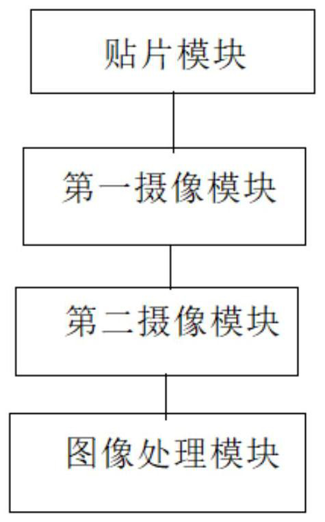
[0072] An accuracy compensation system suitable for placement machines in this embodiment is used for placement machines, and is characterized in that it includes:

[0073] The placement module is used to control the placement head of the placement machine to pick up and place the electronic components to complete the placement function;

[0074] The first camera module is used to obtain the top-view mounting image of the placement head through the first camera pre...


PUM


Abstract

The invention provides a precision compensation system suitable for a chip mounter, and the system comprises a first camera, a second camera, a chip mounting head, an image processing module and a control module, wherein the first camera is used for acquiring image information of an actual mounting element of the chip mounting head; the second camera is used for acquiring image information of a standard mounting element preset on the PCB; characteristic parameters of the actual mounting element are calculated according to the image information of the actual mounting element, and the characteristic parameters of the actual mounting element are compared with characteristic parameters of a standard mounting element to obtain a comparison result; according to the obtained comparison result, the air valve of the suction nozzle on the mounting head sheet is controlled to be closed or opened so as to confirm whether the element is mounted or not. By comparing the information images of the actual mounting element and the standard mounting element, whether the center coordinate and the deflection angle of the adsorbed actual mounting element meet the preset requirements or not is judged toprompt the mounting accuracy.

Description

technical field [0001] The invention relates to the technical field of placement machines, in particular to an accuracy compensation system suitable for placement machines. Background technique [0002] With the changes of the times and the continuous development of science and technology, in the production and manufacture of integrated circuits, the emergence of placement machines has greatly improved the efficiency of integrated circuit production and manufacturing. [0003] Today's placement machine mounts the electronic components on the PCB board through the single-chip microcomputer control program after the placement head picks up the electronic components to complete the placement work. However, there is a problem when the electronic components are mounted on the PCB board. Because the pick-and-place machine picks up the electronic components during the placement process, the angle of the electronic components will deflect when picking up, and it cannot be accurately...

Claims


Application Information

Patent Timeline
IPC IPC(8): H05K13/08H05K13/04H05K3/32
CPCH05K3/32H05K13/046H05K13/0812H05K13/0813H05K13/0818
Inventor 李承浩金英珉金奉焕
Owner 爱微(江苏)电力电子有限公司
Why Eureka
Try Eureka