
Shell structure of energy-absorbing air conditioner, air conditioner and automobile

An air-conditioning shell and shell technology, which is applied to vehicle components, air handling equipment, heating/cooling equipment, etc., can solve the problems of increasing knee damage, passenger leg damage, hard structure, etc., and achieves increased collision Crash space, the effect of avoiding permanent damage

Active Publication Date: 2022-01-11
DONGFENG VISTEON AUTOMOTIVE TRIM SYST CO LTD
View PDF10 Cites 0 Cited by
  • Summary
  • Abstract
  • Description
  • Claims
  • Application Information

AI Technical Summary

Problems solved by technology

[0002] With the progress of society and the improvement of people's living standards, convenient and fast travel methods are more and more accepted by the public, and the number of vehicles driving on the road is also increasing. At the same time, the disadvantage of traffic accidents is that Gradually increasing; therefore, the safety of the occupants in the cab has gradually attracted people's attention. In many cases, the head and knees of the occupants will hit the instrument panel when a traffic accident occurs. If there is a relatively solid structure on the instrument panel, then May cause head and knee injuries to occupants
[0003] Now the general models are basically equipped with airbags to protect the occupants' heads, but due to cost considerations, only some mid-to-high-end models are equipped with knee airbags, which leads to the lack of protection for occupants' knees in some models, thus increasing the The risk of knee injury; and the central area inside the instrument panel is often equipped with a large-sized air conditioner, and the structure is relatively hard. When the vehicle collides, the occupant's leg hits the instrument panel, and then pushes against the hard air conditioner. A large reaction force is generated, causing damage to the passenger's legs

Method used


Image

  • Shell structure of energy-absorbing air conditioner, air conditioner and automobile
  • Shell structure of energy-absorbing air conditioner, air conditioner and automobile
  • Shell structure of energy-absorbing air conditioner, air conditioner and automobile

Examples


Embodiment Construction

[0023] In order to make the purpose, technical solutions and advantages of the embodiments of the present invention clearer, the technical solutions in the embodiments of the present invention will be clearly and completely described below in conjunction with the drawings in the embodiments of the present invention. Obviously, the described embodiments It is a part of embodiments of the present invention, but not all embodiments. Based on the embodiments of the present invention, all other embodiments obtained by persons of ordinary skill in the art without making creative efforts belong to the protection scope of the present invention.

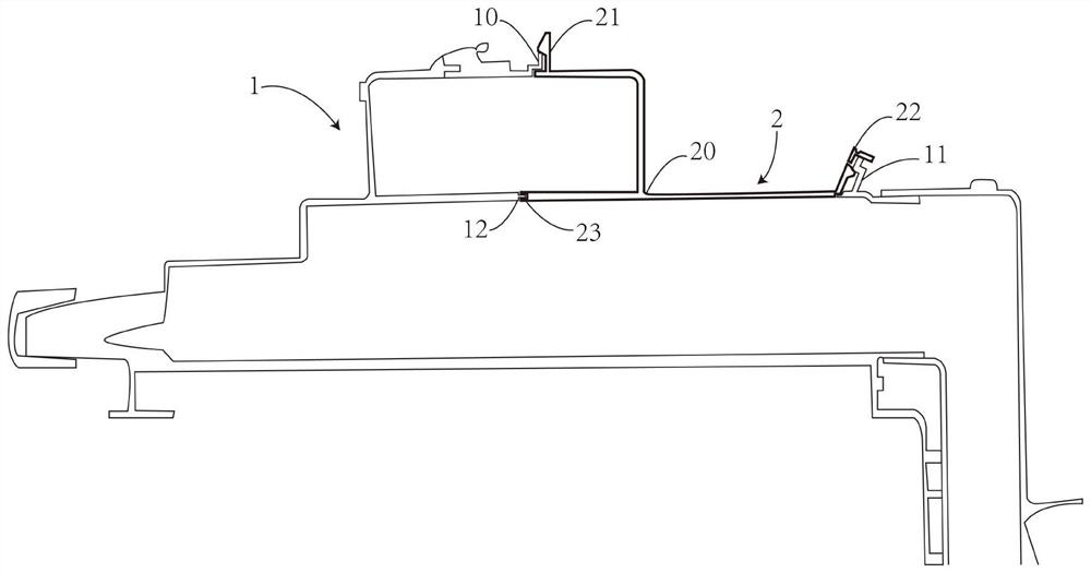
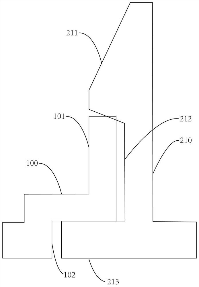
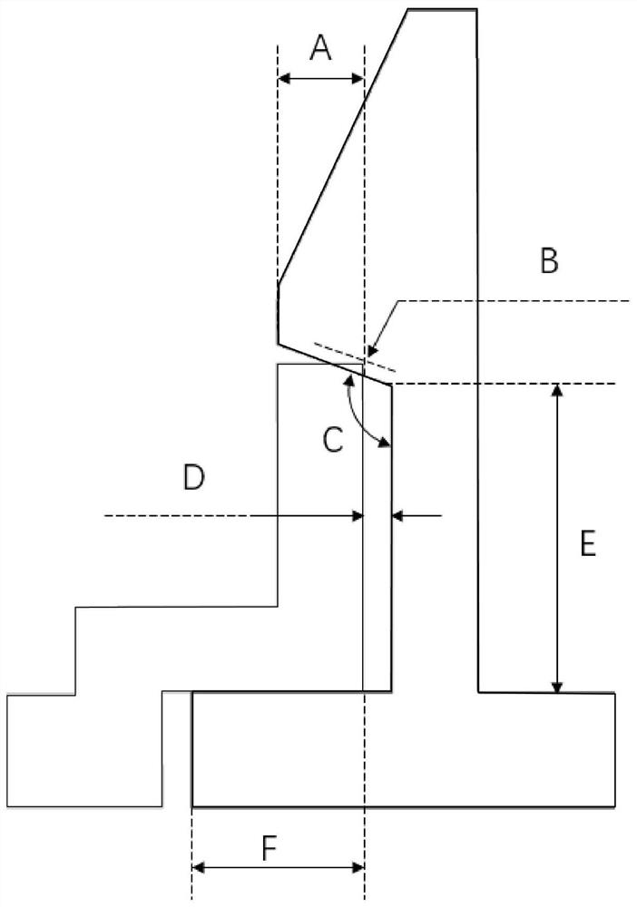
[0024] see figure 1 As shown; the embodiment of the present invention provides an energy-absorbing air conditioner shell structure, including a shell body 1 and a snap-fit ​​structure 2; the shell body 1 includes a first protrusion 10 protruding from the shell body 1, a second Two protrusions 11 and a third protrusion 12; the locking structu...


PUM


Abstract

The invention relates to an energy-absorbing air conditioner shell structure, an air conditioner and an automobile. The energy-absorbing air conditioner shell structure includes a shell main body and a clamping structure; the shell main body includes a first protrusion protruding from the shell main body , the second protrusion and the third protrusion; the clamping structure includes a clamping main body, a first clamping part protruding from the clamping main body, a second clamping part and a third clamping part, the first clamping part A clamping part, the second clamping part and the third clamping part are integrally formed; wherein, the first clamping part is engaged with the first projection, and the second clamping part part is engaged with the second protrusion, and the third engaging part is engaged with the third protrusion; therefore, the collapsing space of the leg is increased, and the reaction force value of the leg is avoided. Continue to ascend and cause permanent damage to the knee.

Description

technical field [0001] The invention relates to the technical field of automobile interior decoration, in particular to an energy-absorbing air conditioner shell structure, an air conditioner and an automobile. Background technique [0002] With the progress of society and the improvement of people's living standards, convenient and fast travel methods are more and more accepted by the public, and the number of vehicles driving on the road is also increasing. At the same time, the disadvantage of traffic accidents is that Gradually increasing; therefore, the safety of the occupants in the cab has gradually attracted people's attention. In many cases, the head and knees of the occupants will hit the instrument panel when a traffic accident occurs. If there is a relatively solid structure on the instrument panel, then Head and knee injuries to occupants may result. [0003] Now the general models are basically equipped with airbags to protect the occupants' heads, but due to ...

Claims


Application Information

Patent Timeline
Patent Type & Authority Patents(China)
IPC IPC(8): B60H1/00
CPCB60H1/00514
Inventor 黄浩陈克琴宋全喜
Owner DONGFENG VISTEON AUTOMOTIVE TRIM SYST CO LTD
Learn More