Connecting structure for prefabricated concrete wall and concrete edge columns and construction method

A prefabricated concrete and concrete wall technology, applied in the direction of columns, walls, pier columns, etc., can solve the problems of unreliable connection and low construction accuracy requirements, and achieve the effects of good integrity, reduced cast-in-place operations, and shortened time spent

Pending Publication Date: 2021-02-19
SOUTH CHINA UNIV OF TECH +1
View PDF0 Cites 0 Cited by
  • Summary
  • Abstract
  • Description
  • Claims
  • Application Information

AI Technical Summary

Problems solved by technology

[0003] The purpose of the present invention is to overcome the deficiencies in the prior art, provide a connection structure between prefabricated concrete walls and concrete edge columns, solve the problem of unreliable connection between existing prefabricated concrete walls and concrete edge columns, and facilitate construction. Construction accuracy is not high

Method used


Image

  • Connecting structure for prefabricated concrete wall and concrete edge columns and construction method
  • Connecting structure for prefabricated concrete wall and concrete edge columns and construction method
  • Connecting structure for prefabricated concrete wall and concrete edge columns and construction method

Examples


Embodiment

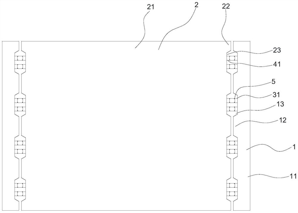
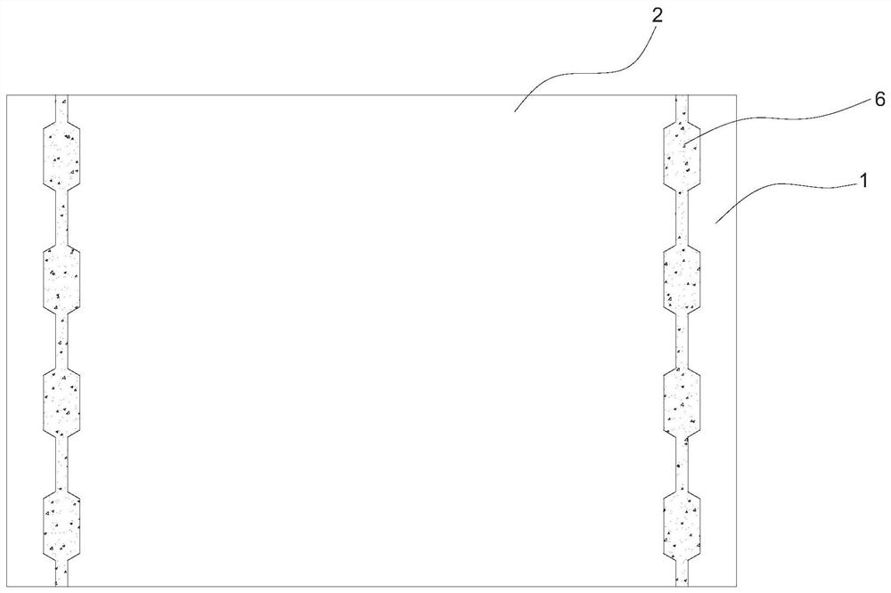
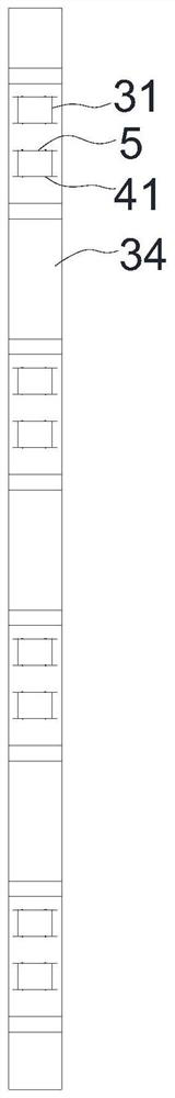
[0031] Such as figure 1 , figure 2 and image 3 As shown, this embodiment provides a connection structure between a prefabricated concrete wall and a concrete edge column, including a concrete edge column 1, a concrete wall 2, a first vertical stirrup 31, a second vertical stirrup 41 and a connecting stirrup 5.

[0032] Such as figure 1 , Figure 4 and Figure 5 As shown, two concrete edge columns are located on both sides of the concrete wall. The concrete edge columns include a column body 11 and a first protrusion 12, and a plurality of first protrusions are arranged longitudinally at intervals on one side of the column body. There is a first groove 13 between the two first protrusions, and the first vertical stirrup is connected with the concrete edge column and is located in the first groove; the concrete edge column includes the edge column steel frame and is poured on the edge column steel frame concrete, the edge column reinforcement frame includes the first lon...


PUM


Abstract

The invention discloses a connecting structure for a prefabricated concrete wall and concrete edge columns and a construction method. The connecting structure comprises the concrete edge columns, theconcrete wall, first vertical stirrups, second vertical stirrups and connecting stirrups, wherein each concrete edge column comprises a column body and first protruding parts, the plurality of first protruding parts are longitudinally distributed on one side of each column body at intervals, a first groove is formed between every two adjacent first protruding parts, and the first vertical stirrupsare connected with the concrete edge columns and located in the first grooves; the concrete wall comprises a wall body and second protruding parts, a plurality of second protruding parts are longitudinally distributed on the two sides of the wall body at intervals, a second groove is formed between every two adjacent second protruding parts, and the second vertical stirrups are connected with theconcrete wall and located in the second grooves; and the first vertical stirrups and the second vertical stirrups are bound through the connecting stirrups, the first protruding parts and the secondprotruding parts are opposite, gaps exist between the first protruding parts and the second protruding parts, and concrete is poured on the first vertical stirrups, the second vertical stirrups and the connecting stirrups to form a cast-in-place stripe.

Description

technical field [0001] The invention relates to the technical field of prefabricated concrete structure buildings, in particular to a connection structure and a construction method of a prefabricated concrete wall and a concrete edge column. Background technique [0002] The prefabricated concrete structure has the advantages of fast construction speed, energy saving and environmental protection, and a small amount of on-site construction work. In recent years, it has developed rapidly in my country. Commonly used prefabricated structures include edge columns and shear walls. How to form two prefabricated structures into a prefabricated system become an important issue for civil engineers. In the past, for the connection of assembly structures, the method of connecting steel bars and then pouring concrete or grouting at the connection was mainly used, but the quality of their connection parts could not be guaranteed. In addition, some engineers proposed the method of key conn...

Claims


Application Information

Patent Timeline
Patent Type & Authority Applications(China)
IPC IPC(8): E04B1/38E04B2/56E04C3/34
CPCE04B1/383E04B2/56E04C3/34
Inventor 左志亮李朋原蔡健陈祺荣张伟生陈庆军朱东烽杨春江幸莲姜正荣
Owner SOUTH CHINA UNIV OF TECH
Why Eureka
Try Eureka