
Automatic alarm door stopper

An automatic alarm and door blocker technology, used in alarms, burglar alarms, switches with brakes, etc., can solve the problems of door panel damage and poor door blocking effect.

Inactive Publication Date: 2021-02-19
刘亚明
View PDF9 Cites 0 Cited by
  • Summary
  • Abstract
  • Description
  • Claims
  • Application Information

AI Technical Summary

Problems solved by technology

[0005] Aiming at the deficiencies of the prior art, the present invention provides an automatic alarm door stopper, which has the advantages of good door blocking effect and can reduce the damage to the door panel caused by fast pushing the door. The problem of damage caused by door panels

Method used


Image

  • Automatic alarm door stopper
  • Automatic alarm door stopper
  • Automatic alarm door stopper

Examples


Embodiment 1

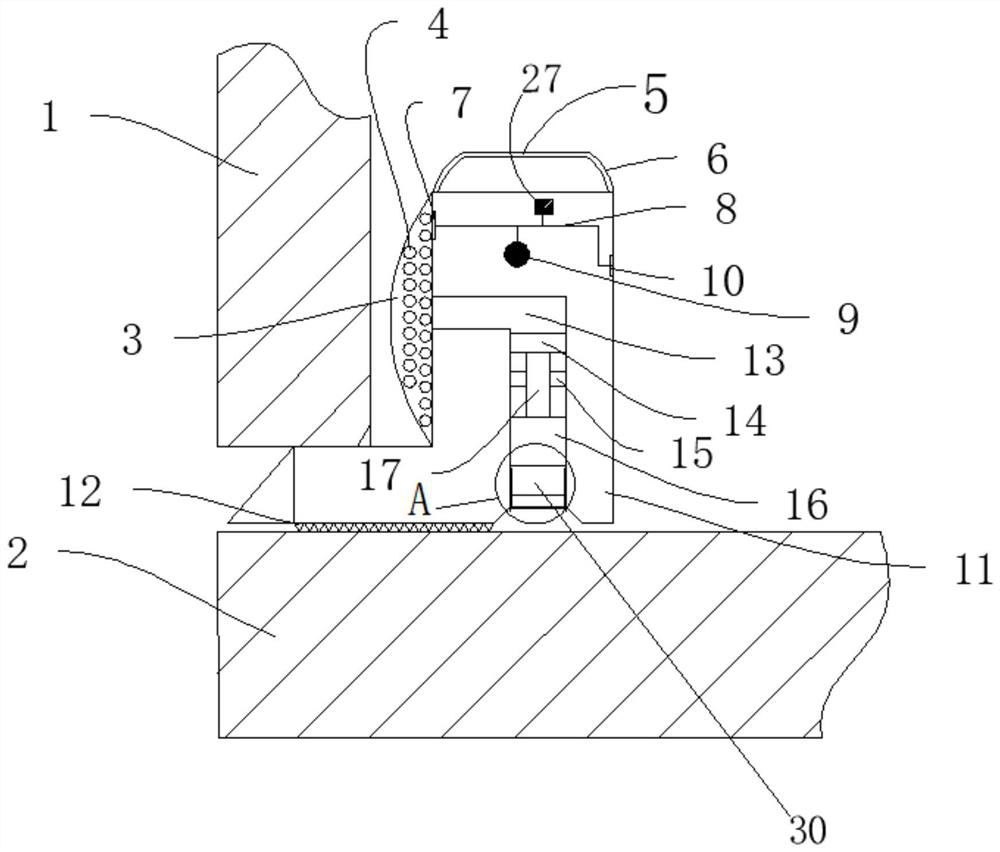
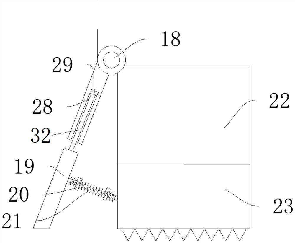
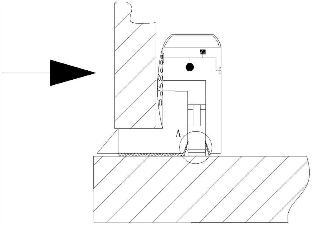
[0028] see Figure 1-4 , an automatic alarm door stopper, comprising a housing 11, the housing 11 is arranged in the gap between the door 1 and the floor 2, the two ends of the top of the housing 11 are provided with support rods 6, the support rods 6 and the handle The rods 5 are connected, and a sliding groove 13 is provided in the housing 11. The sliding groove 13 is L-shaped, and one end of the L-shape is located at the bottom of the housing 11, and the other end is located on the left side of the housing 11. The left side of the housing 11 is provided with a storage The bag 3 and the storage bag 3 are made of soft cotton material, and an inflatable sponge ball 4 is placed inside the storage bag 3. The side of the storage bag 3 near the sliding groove 13 is provided with a ventilating film, and the gas in the inflatable sponge ball 4 can pass through after being compressed. The ventilation film enters the sliding groove 13, and a piston structure is slidably connected in t...

Embodiment 2

[0033] see Figure 5 The difference between the present embodiment and the first embodiment is that: the housing 11 is provided with a U-shaped air-filling groove 24 located below the sliding groove 13 and opening to the left, and one end of the U-shaped air-filling groove 24 is connected with the ventilation film. The other end of the U-shaped inflatable groove 24 is provided with an elastic support sheet groove 25 positioned at the door 1 below, and an elastic support sheet 26 is placed in the elastic support sheet groove 25, and the elastic support sheet 26 is made of elastic cotton airtight material.

[0034]In this embodiment, the door is opened by squeezing the inflatable sponge ball 4, the gas passes through the sliding groove 13 and the 匚-shaped inflatable groove 24, and the gas in the 匚-shaped inflatable groove 24 squeezes the elastic support piece 26, so that the elastic support piece 26 is squeezed and bent upwards. Under force, it is close to the bottom of door 1, ...


PUM


Abstract

The invention relates to the technical field of door stoppers, and discloses an automatic alarm door stopper. The automatic alarm door stopper comprises a shell which is arranged in a gap between a door and a floor. A sliding groove is formed in the shell. The sliding groove is in an L shape, one end of the L shape is located at the bottom of the shell, and the other end of the L shape is locatedon the left side of the shell. A storage bag is arranged on the left side of the shell. An inflatable sponge ball is placed in the storage bag. A ventilation film is arranged on the side, close to thesliding groove, of the storage bag. Air in the inflatable sponge ball can enter the sliding groove through the ventilation film after being compressed. A piston structure is connected into the sliding groove in a sliding mode. The piston structure comprises a first piston block, a piston connecting block and a second piston block which are sequentially connected with one another, the outer side of the piston connecting block is sleeved with an annular limiting block, and a piston supporting component is arranged below the second piston block. The automatic alarm door stopper has the advantages of being good in door stop effect and capable of reducing damage of rapid door pushing to a door plate.

Description

technical field [0001] The invention relates to the technical field of door stoppers, in particular to an automatic alarm door stopper. Background technique [0002] With the development of social life, there are fewer and fewer social security cases in our country, but in relatively remote rural areas or towns, there are still many cases of burglary, robbery, and rape, and the public security management is poor. Generally, burglary and theft will choose doors and windows to enter , Most of them will choose to pry open the door to enter. This kind of office, hotel, dormitory, this kind of non-long-term residence, there will always be psychological worries, psychological and physical anxiety and trauma when living in it. At this time, you need to use some Non-permanent devices are used to fix the door to improve the sense of security of the door. When sleeping at night, people are in a state of alert and will be anxious about safety issues. Some safety measures will be taken,...

Claims


Application Information

Patent Timeline
Patent Type & Authority Applications(China)
IPC IPC(8): E05C19/00E05F5/06G08B21/24G08B3/10G08B15/00
CPCE05C19/00E05F5/06G08B21/24G08B3/10G08B15/00
Inventor 刘亚明
Owner 刘亚明
Learn More