
Intelligent face recognition device

A face recognition and face recognition technology, applied in the field of face recognition, can solve the problems of trouble, no protective structure, damage to the display screen of the face recognition device, etc.

Active Publication Date: 2021-02-19
江苏禾嘉电子科技有限公司
View PDF9 Cites 1 Cited by
  • Summary
  • Abstract
  • Description
  • Claims
  • Application Information

AI Technical Summary

Problems solved by technology

[0004] Aiming at the problems in the prior art, the present invention provides an intelligent face recognition device, which solves the problem that most of the current installations are directly fixed on the access control, and the angle cannot be adjusted. The camera part of the recognition device cannot collect the facial information of the people entering and leaving. At this time, the tall people entering and leaving need to bend down to align their faces with the camera part of the face recognition device. Most of the face recognition devices do not have a protective structure outside. If the face recognition device is accidentally hit, the force generated during the impact will directly act on the display screen of the face recognition device, resulting in damage to the display screen of the face recognition device. , affect the subsequent use, and when the staff operates on the display screen of the face recognition device, if there is sweat on the fingers, the sweat will follow the fingers and stick to the display screen of the face recognition device during operation, and then form stains, which need The staff use cleaning tools to clean the display screen of the face recognition device, which is inconvenient

Method used


Image

  • Intelligent face recognition device
  • Intelligent face recognition device
  • Intelligent face recognition device

Examples


Embodiment Construction

[0029] In order to make the technical means, creative features, goals and effects achieved by the present invention easy to understand, the present invention will be further described below in conjunction with specific embodiments.

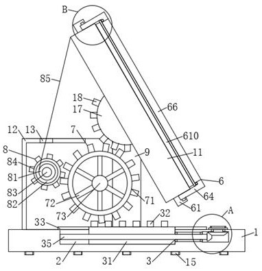
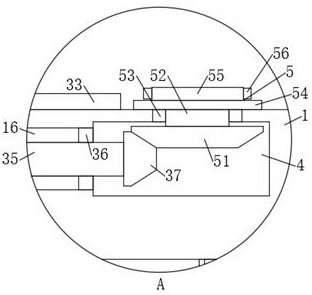
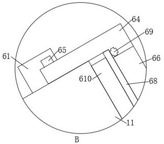
[0030] Such as Figure 1-Figure 10 As shown, an intelligent face recognition device according to the present invention includes a seat plate 1, a first chute 2 is opened in the middle of the upper end of the seat plate 1, and a driving mechanism is installed inside the first chute 2 3. There is a cavity 4 inside part of the seat plate 1 on one side of the first chute 2, the cavity 4 and the first chute 2 are located on the same center line, and the upper side wall of the cavity 4 A rotating mechanism 5 is installed on it, the rotating mechanism 5 is connected with the driving mechanism 3, a through hole 16 is opened between the cavity 4 and the first chute 2, and the front and rear sides of the upper middle part of the seat plate 1 are fixed A ve...


PUM


Abstract

The invention relates to the field of face recognition, in particular to an intelligent face recognition device. The device comprises a base plate, a first sliding groove is formed in the middle of the upper end of the base plate, and a driving mechanism is installed in the first sliding groove. A face recognition device body of the device is rotationally connected to two vertical plates through amounting shaft, and a transmission mechanism is mounted in a shell and connected with the driving mechanism and a winding mechanism; and when the face recognition device is used, a sliding plate of the driving mechanism can slide in the first sliding groove, the sliding plate rotates a driving gear ring of the driving mechanism through a first toothed plate, the driving gear ring stirs the face recognition device body through a second toothed plate, meanwhile, a winding pipe of the winding mechanism is driven to wind a connecting rope, the face recognition device body is pulled through the connecting rope, the face recognition device body is made to rotate between the two vertical plates, the angle of the face recognition device body is adjusted, face information of tall people in and outcan be collected conveniently, and the time of people in and out is prevented from being delayed.

Description

technical field [0001] The invention relates to the field of face recognition, in particular to an intelligent face recognition device. Background technique [0002] The face recognition system takes face recognition technology as the core. It is an emerging biometric technology and a high-tech technology in the field of international science and technology. It integrates the principles of science and technology, uses computer image processing technology to extract portrait feature points from video, and uses the principle of biostatistics to analyze and establish mathematical models, which has broad development prospects. Face recognition devices are installed on the access control of many communities to ensure that safety within. [0003] Most of the currently used ones are directly fixed on the access control during installation, and the angle cannot be adjusted. If the height of the person entering and leaving is high, the camera part of the face recognition device cann...

Claims


Application Information

Patent Timeline
Patent Type & Authority Applications(China)
IPC IPC(8): F16M13/02F16M11/04F16M11/10F16M11/18G06K9/00B08B1/00G12B17/08
CPCF16M13/02F16M11/043F16M11/10F16M11/18B08B1/00G12B17/08G06F18/00
Inventor 彩志红
Owner 江苏禾嘉电子科技有限公司
Learn More