Hot blast stove of drying equipment

A technology of drying equipment and hot blast stove, applied in lighting and heating equipment, air heaters, fluid heaters, etc., can solve problems affecting equipment use, equipment ash adhesion, slow cooling of residual temperature

Inactive Publication Date: 2021-02-19
南安昊捷商贸有限公司
View PDF0 Cites 2 Cited by
  • Summary
  • Abstract
  • Description
  • Claims
  • Application Information

AI Technical Summary

Problems solved by technology

[0004] The hot gas generated after the fuel is burned in the combustion chamber is circulated outdoors and mixed with the outside air. Since the hot gas will carry the burnt fuel slag, it also contains sparks and the residual temperature cools slowly, and mixes with the air. After that, they will be discharged from the hot air outlet together to supply heat to the drying equipment, which will easily cause ash to adhere to the equipment and affect the use of the equipment.

Method used


Image

  • Hot blast stove of drying equipment
  • Hot blast stove of drying equipment
  • Hot blast stove of drying equipment

Examples


Embodiment 1

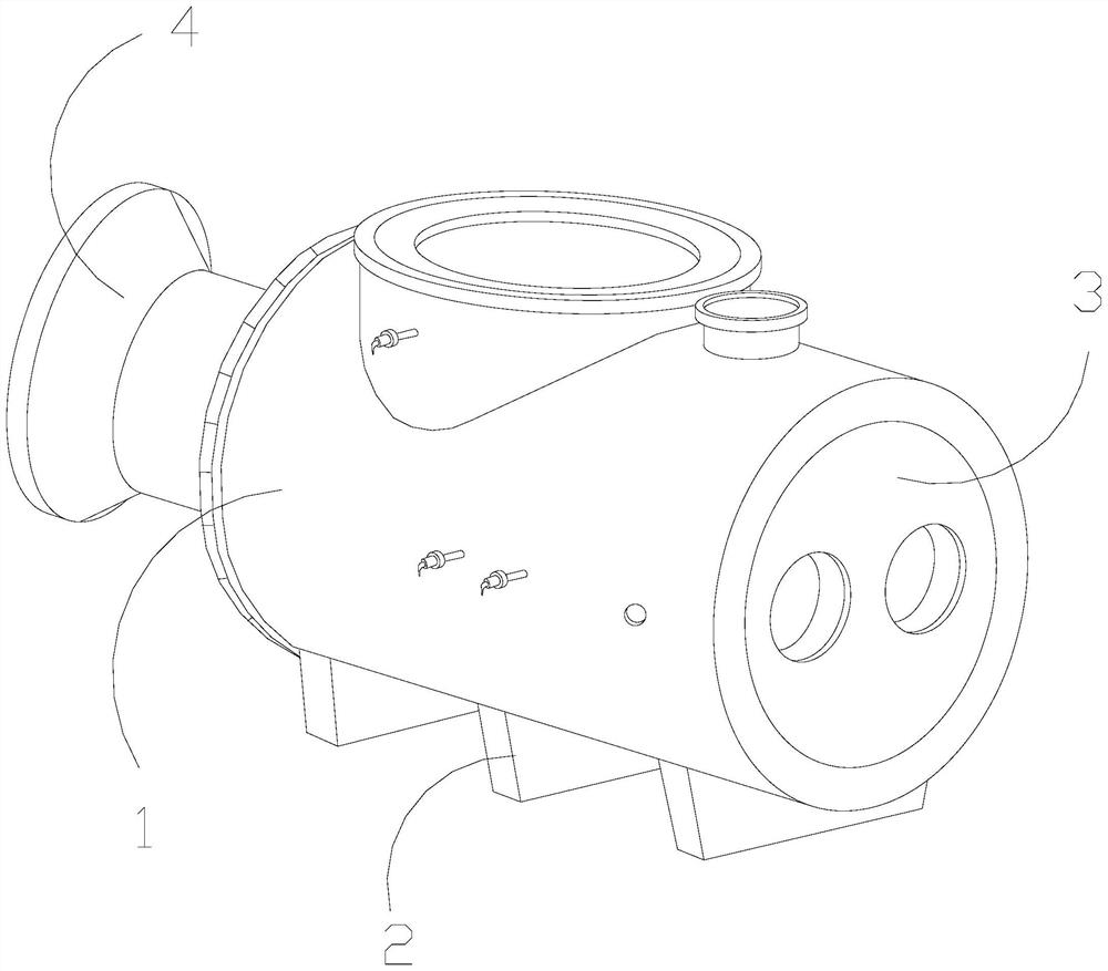
[0028] as attached figure 1 To attach Figure 6 Shown:

[0029] The invention provides a hot blast stove for drying equipment, which is structured with a furnace body 1, a support 2, an air inlet door 3, and a burner 4. The support 2 is welded and connected to the bottom of the furnace body 1, and the air inlet door 3 is movably engaged with and communicated with the furnace body 1 , and the burner 4 is connected to one side end of the furnace body 1 through.

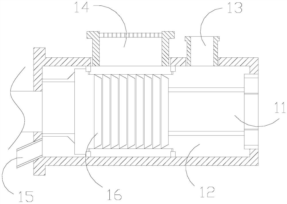
[0030] The furnace body 1 is provided with an air inlet duct 11, a circulation chamber 12, a smoke outlet 13, a hot gas outlet 14, a slag outlet 15, and a heat generating device 16, and the air inlet duct 11 is embedded and installed inside the furnace body 1 , the circulation chamber 12 and the furnace body 1 are of an integrated structure and located inside it, the smoke exhaust port 13 is connected through the top of the furnace body 1, and the hot gas discharge port 14 is arranged beside the smoke exhaust port 13,...

Embodiment 2

[0036] as attached Figure 7 To attach Figure 8 Shown:

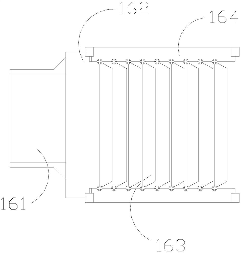
[0037]Wherein, the heat mixing body 163 is provided with a hinge plate 631 and an elliptical flow path 632, and the elliptical flow path 632 is embedded in the hinge plate 631, and the hinge plate 631 is a trapezoidal plate body, and the elliptical flow path There are four diameters 632, which are evenly distributed on the hinge plate 631. When the hinge plate 631 swings, the elliptical flow path 632 is used for the gas to pass through multiple flow paths, and at the same time drive the speed of the airflow, and assist the hinge plate 631. swing force.

[0038] Wherein, the elliptical flow path 632 is provided with a movable cavity 321, a spring 322, a displacement ring 323, a chisel column 324, and a diameter cavity 325, the spring 322 moves inside the movable cavity 321, and the displacement ring 323 is connected with the spring 322 And movable cooperation, the chisel column 324 is fixedly connected with the inner ...


PUM


Abstract

The invention discloses a hot blast stove of drying equipment. The hot blast stove structurally comprises a stove body, supports, an air inlet door and a combustor. Airflow generated by swinging of heat mixing bodies exerts airflow force on rotating bodies to enable the rotating bodies to continuously rotate around bearings, circulation of heat gas is disturbed in a certain flow direction at a flow discharging opening, circulation of spark foam carried in the gas is blocked on the inner side of a middle partition mechanism and stays and suspends for a long time, so that sparks are cooled and extinguished conveniently, inclined impact blocks deform obliquely under the action of airflow force to extinguish the spark foam carried in the gas, circulation and mixing of the gas are accelerated through hinged swing movement of the heat mixing bodies, swing of hinge swing plates has interaction force on airflow, at the moment when the hinge swing plates move in the opposite direction of the airflow, the spark foam can be extinguished through beating under elastic cooperation of springs, a displacement ring conducts multi-directional annular displacement movement to drive chisel columns tobe inserted in different positions in a radial cavity in a penetrating manner, the spark foam flowing through the chisel columns are extinguished through chisel columns, and therefore the spark foam in the mixed gas is eliminated.

Description

technical field [0001] The invention belongs to the field of drying equipment, and more specifically relates to a hot blast stove of the drying equipment. Background technique [0002] Drying equipment is usually a device that uses warm and hot air to dry the materials to be dried. As its thermal power machine, the hot air stove generates heat by burning coal, gas, etc., and mixes it with circulating air through the heating surface to make it a Hot air, and then conduct the hot gas to the drying equipment. [0003] Based on the inventor's discovery above, the hot blast stove of existing drying equipment has the following deficiencies: [0004] The hot gas generated after the fuel is burned in the combustion chamber is circulated outdoors and mixed with the outside air. Since the hot gas will carry the burnt fuel slag, it also contains sparks and the residual temperature cools slowly, and mixes with the air. Finally, they are discharged from the hot air outlet together to s...

Claims


Application Information

Patent Timeline
Patent Type & Authority Applications(China)
IPC IPC(8): F24H3/04F24H9/00F24H9/18F23J1/02
CPCF23J1/02F24H3/0488F24H9/0052F24H9/1881Y02B30/00
Inventor 梁子定
Owner 南安昊捷商贸有限公司
Why Eureka
Try Eureka