Tearing force testing equipment for cloth production

A technology for testing equipment and fabrics. It is applied in the direction of applying stable tension/pressure to test the strength of materials, measuring devices, and analyzing materials. It can solve problems such as high labor intensity, easy soreness in the arms, and easy soreness.

Inactive Publication Date: 2021-02-19
祝汪林
View PDF1 Cites 0 Cited by
  • Summary
  • Abstract
  • Description
  • Claims
  • Application Information

AI Technical Summary

Problems solved by technology

[0005] In order to overcome the shortcomings of traditional fabric tearing force testing, such as high labor intensity, inconvenient operation, and easy soreness of the arm, the technical problem of the present invention is to provide a tearing force test for fabric production that is less labor intensive, easy to operate, and prevents easy soreness of the arm. Test Equipment

Method used


Image

  • Tearing force testing equipment for cloth production
  • Tearing force testing equipment for cloth production
  • Tearing force testing equipment for cloth production

Examples


Embodiment 1

[0058] A kind of tear force testing equipment for cloth production, such as figure 1 As shown, it includes a bracket 1, a panel 2, a first support frame 3, a clamping mechanism 4 and a pushing mechanism 5. The top of the two brackets 1 is provided with a panel 2, and the top of the front side of the panel 2 is provided with a first support frame 3. The panel 2. A clamping mechanism 4 is provided on the front side, and a pushing mechanism 5 is provided on the left and right sides of the panel 2.

[0059] When people want to test the tearing force of the cloth, they can use this tearing force testing equipment for cloth production. First, the user places the cloth in the clamping mechanism 4 to clamp the cloth, and then starts the pushing mechanism 5 , push the fabric backwards, transport the fabric to carry out the tear force test, when the test is completed, close the push mechanism 5 .

Embodiment 2

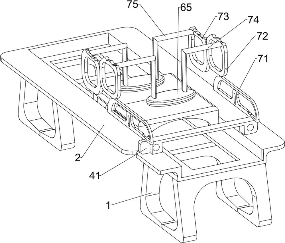
[0061] On the basis of Example 1, such as figure 2 and image 3 As shown, the clamping mechanism 4 includes a push block 41, a lower pressing plate 42, a first sliding column 43 and a first spring 44, the front side of the panel 2 is slidingly provided with a push block 41, and the left and right sides of the top of the push block 41 are provided with The first sliding column 43, the lower pressing plate 42 is slidably connected between the bottoms of the two first sliding columns 43, the first spring 44 is wound around the top of each first sliding column 43, and the top of each first spring 44 is connected to the top of each first sliding column 43. The first sliding column 43 is connected, and the bottom end of each first spring 44 is connected with the lower pressing plate 42 .

[0062] The user pulls the lower pressing plate 42 upward, thereby driving the lower pressing plate 42 to move upward, the first spring 44 is compressed, the cloth is placed on the pushing block ...

Embodiment 3

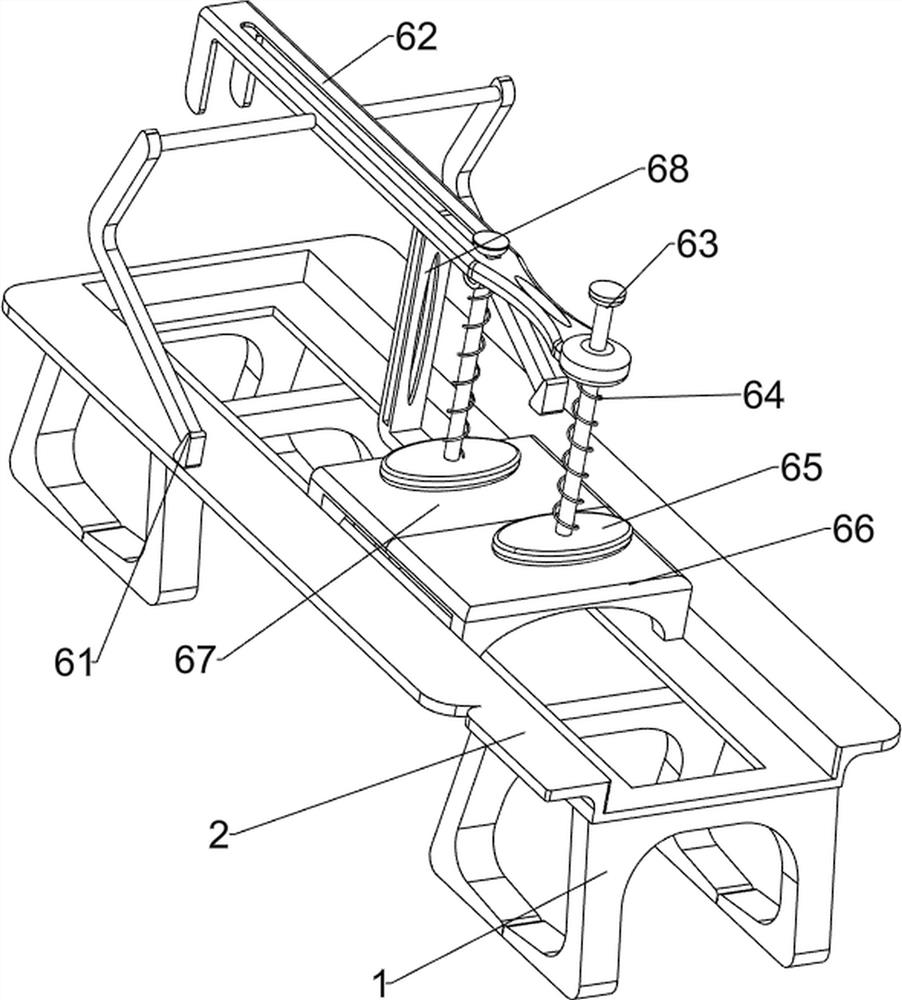
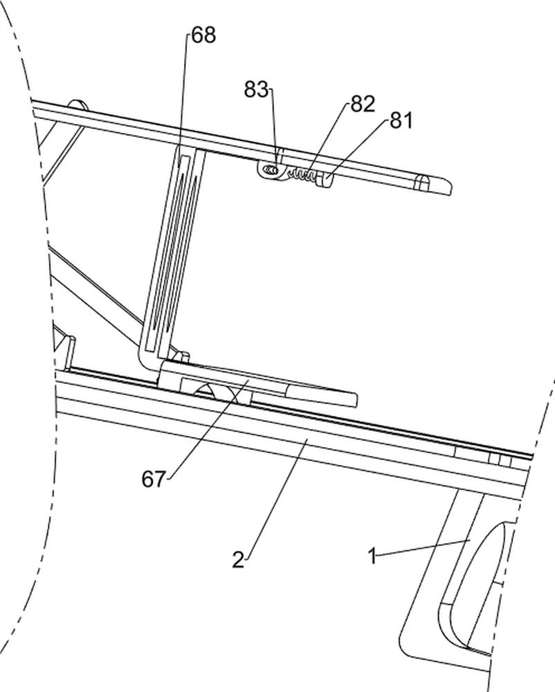
[0066] On the basis of Example 2, such as Figure 4-Figure 7 As shown, an extruding mechanism 6 is also included, and the middle part of the inner wall of the panel 2 is provided with an extruding mechanism 6. The extruding mechanism 6 includes a second support frame 61, a groove block 62, a second sliding column 63, a second spring 64, Extruding block 65, first pressing plate 66, second pressing plate 67 and third fixing block 68, two second supporting frames 61 are arranged on the rear side of panel 2, groove block 62 is arranged between two second supporting frames 61 , the front middle part of the groove block 62 is slidingly provided with two second sliding columns 63, and the bottom end of each second sliding column 63 is provided with an extruding block 65, and each second sliding column 63 is wound with a second Spring 64, the top of every second spring 64 is all connected with groove block 62, and the bottom end of every second spring 64 is all connected with extrudin...


PUM


Abstract

The invention relates to testing equipment, particularly to tearing force testing equipment for cloth production. The tearing force testing equipment for cloth production is low in labor intensity, convenient to operate and capable of preventing arms from aching easily, and comprises: two brackets, wherein a panel is arranged at the tops of the two brackets; a first support frame arranged at the top of the front side of the panel; a clamping mechanism arranged on the front side of the panel; and pushing mechanisms arranged on the left side and the right side of the panel. According to the invention, by loosening a lower pressing plate, a first spring resets, so that the lower pressing plate is driven to move downwards to clamp cloth so as to achieve the clamping effect; and the telescopicrod of an air cylinder extends backwards to drive a pushing block to move backwards, and the pushing block moves backwards according to the track of a sliding rail, so that the pushing effect is achieved.

Description

technical field [0001] The invention relates to a testing device, in particular to a tearing force testing device for fabric production. Background technique [0002] After the fabric is produced, it is necessary to test the tearing force of the fabric. The traditional tearing force test of the fabric is through people fixing the tensioners at both ends of the fabric, and then people hold the two tensioners to tear the fabric, and test the tension on the tensioner. In this process, people’s labor intensity is high, and the arm is prone to soreness when tearing for a long time, but the fixed area between the tensioner and the other end of the fabric is small, causing the tensioner to easily fall from the fabric. [0003] Patent application CN109297819A, with a publication date of 20190201, discloses a cloth tearing force test device, including a base, a frame, a horizontal plate, a cloth roll shaft, a clamping mechanism, an electronic tensioner, a U-shaped frame, a mounting p...

Claims


Application Information

Patent Timeline
Patent Type & Authority Applications(China)
IPC IPC(8): G01N3/02G01N3/04G01N3/10
CPCG01N3/02G01N3/04G01N3/10
Inventor 祝汪林
Owner 祝汪林
Why Eureka
Try Eureka