Embedded firmware remote debugging method and system

A remote debugging and embedded technology, which is applied in software testing/debugging, instrumentation, electrical digital data processing, etc., can solve problems such as low efficiency and inconvenient code modification, and achieve the effect of easy positioning of problems and simplification of debugging links

Active Publication Date: 2021-02-19
NANJING QINHENG MICROELECTRONICS CO LTD
View PDF3 Cites 0 Cited by
  • Summary
  • Abstract
  • Description
  • Claims
  • Application Information

AI Technical Summary

Problems solved by technology

[0004] Purpose of the invention: In order to solve the problems of inconvenient code modification and low efficiency in the process of firmware upgrade and debugging in the prior art, the present invention provides a remote debugging method for embedded firmware

Method used


Image

  • Embedded firmware remote debugging method and system

Examples


Embodiment 1

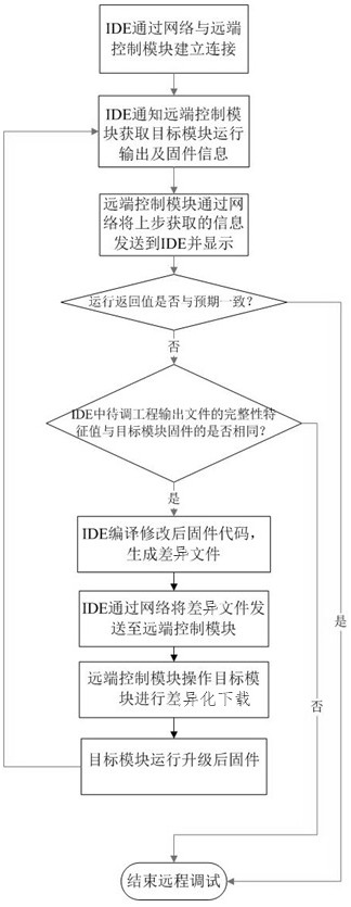
[0024] An embedded firmware remote debugging system, including IDE (MounRiver Studio) and a remote control module,

[0025] The IDE is used to send instructions, receive and display the target module operation output results, receive code modification and generate a differential download file according to the code before and after modification, and the differential download file includes code modification address and modification content;

[0026] The remote control module includes a main control unit, a network unit and a burning unit, and the network unit and the burning unit are all connected to the main control unit; the burning unit is used for burning the target module; the main control unit, the network unit and the burning unit The unit is integrated in a circuit board module.

[0027] The IDE is connected to the network unit of the remote control module through the network. This embodiment uses a 4G network, and other networks can also be used. The programming unit o...

Embodiment 2

[0034] Compared with Embodiment 1, the difference between Embodiment 2 and Embodiment 1 is that the remote control module can also implement the control function by installing a customized APP on the smart terminal, that is, the main control unit is installed on the smart terminal (mobile phone, tablet computer, computer or embedded Since the smart terminal itself has its own network unit, there is no need to set up another network unit, and you can directly use the network function of the smart terminal. The communication between the smart terminal and the target module adopts BLE and serial port, or BLE and USB port to read the information of the target module and burn the target module. Except for this, other contents are the same as those in Embodiment 1.


PUM


Abstract

The invention discloses an embedded firmware remote debugging method and system, and the system comprises an IDE and a far-end control module, the IDE establishes network connection with the far-end control module. The method comprises: by the IDE, sending an instruction to the far-end control module to execute an information collection step, wherein the information comprises target module operation output information, a firmware name and a firmware integrity characteristic value, by the IDE, sending an instruction to the far-end control module to execute a differentiated downloading step, circularly executing the information collection step and the differentiated downloading step until the operation output information of the target module reaches the expectation, wherein on-site debuggingpersonnel do not need to adopt a specific tool for burning, so that the debugging link is simplified, a return result after code execution can be directly seen on the IDE, and field debugging personnel do not need to feed back an operation result according to a visual inspection phenomenon of a target module, so that the problem is easier to position, and a differential transmission and burning mode with integrity check is adopted, so that the transmission security of the data network is ensured, and the debugging efficiency is improved.

Description

technical field [0001] The invention belongs to the field of firmware debugging of embedded products, in particular to a method and system for remote debugging of embedded firmware. Background technique [0002] In the context of the rapid advancement of science and technology, traditional industries and high-tech are constantly colliding and merging, subtly affecting all aspects of contemporary people's lives. With the promotion of a series of cutting-edge applications and technologies such as smart speakers, civilian drones, smart wearable devices, autonomous driving, smart homes, and urban eye systems, the embedded industry has also ushered in new opportunities for development. [0003] Due to the needs of function changes or bug fixes, many embedded products will face the problem of firmware debugging and upgrading after being put into use for a period of time. During remote debugging, it is necessary to send the compiled complete output file to the platform where the b...

Claims


Application Information

Patent Timeline
IPC IPC(8): G06F11/36
CPCG06F11/362G06F11/3644G06F11/3664
Inventor 刘帅刘志斌
Owner NANJING QINHENG MICROELECTRONICS CO LTD
Why Eureka
Try Eureka