Sitting device convenient to sit

A sitting and convenient technology, applied in the field of nursing, can solve problems such as inconvenient movement

Pending Publication Date: 2021-02-23
上海慈通科技有限公司
View PDF0 Cites 0 Cited by
  • Summary
  • Abstract
  • Description
  • Claims
  • Application Information

AI Technical Summary

Problems solved by technology

[0005] In view of the above-mentioned defects of the prior art, the technical problem to be solved by this application is that it is very inconvenient for users to move between seats of different heights

Method used


Image

  • Sitting device convenient to sit
  • Sitting device convenient to sit
  • Sitting device convenient to sit

Examples


Embodiment 1

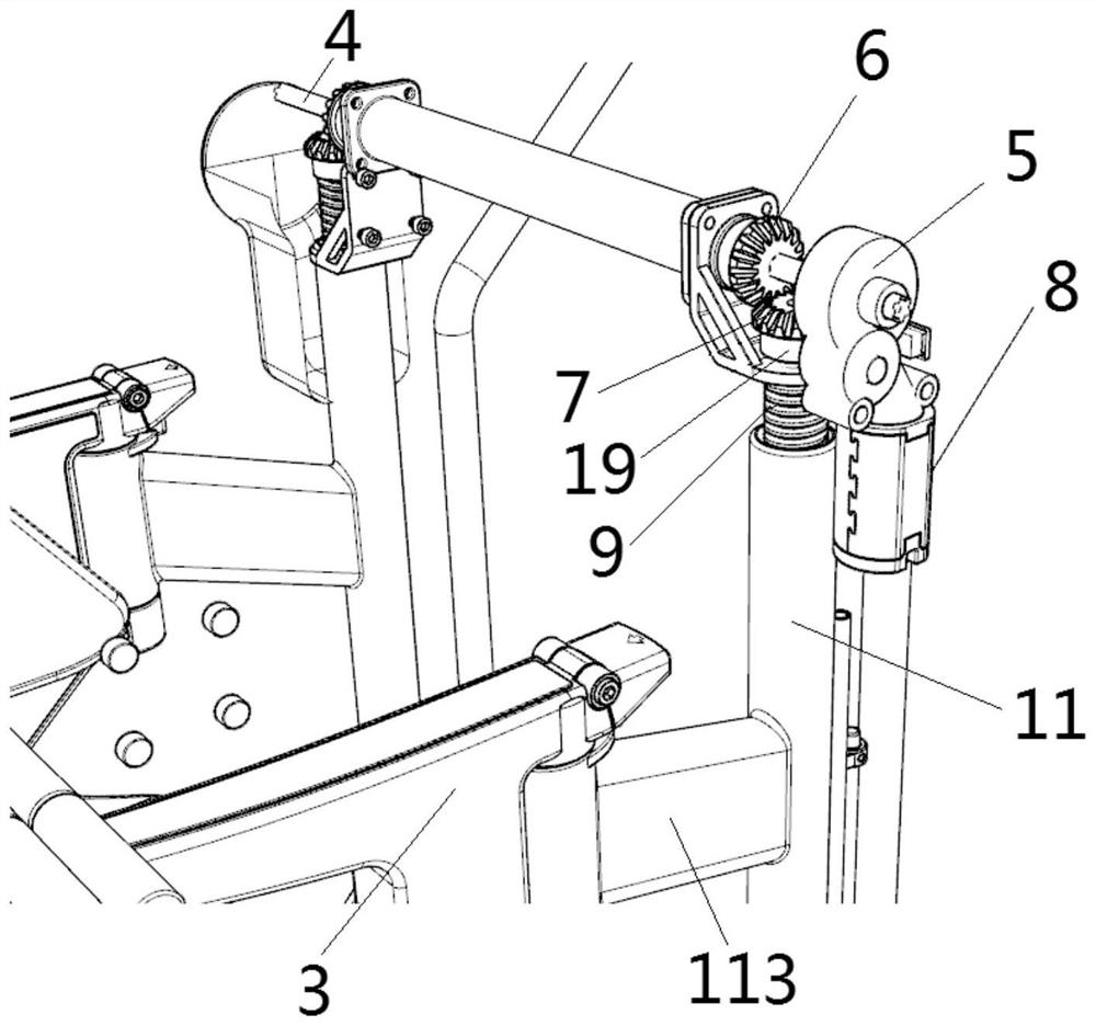
[0081] The distinguishing technical features of this embodiment are: figure 2As shown, each vertical part includes a vertical rod 10 placed up and down, and the top outer surface of the vertical rod 10 is rotatably sleeved with a rotary lifting mechanism. An embodiment of the rotary lifting mechanism includes a screw rod 9, one end of the chair handle 3 A sleeve 11 is fixedly installed, and the inner side wall of the sleeve 11 is provided with an internal thread matching the surface thread of the screw mandrel 9, and the screw mandrel 9 rotates, and the drive sleeve 11 drives the chair handle 3 to move up and down;

[0082] Such as figure 2 As shown, by setting the threaded cooperation between the screw rod 9 and the sleeve 11, the sleeve 11 can be driven to realize the lifting function, thereby having an adjustment effect. The top surface of the rod 9 is fixedly socketed to realize the positioning in the vertical direction without hindering the rotation of the screw rod 9;...

Embodiment 2

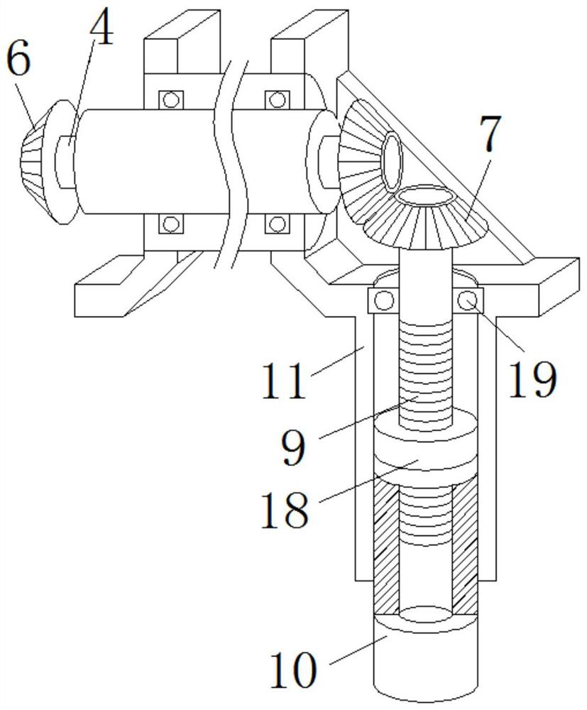
[0103] The difference technical features between this embodiment and embodiment one are: as image 3 As shown, another embodiment of the rotary lifting mechanism, the surface of the vertical rod 10 is sleeved with a sleeve 11, the sleeve 11 is sleeved on the screw rod 9, and the upper end of the sleeve 11 is fixedly connected to the upper end of the screw rod 9 through a bearing 19 ;

[0104] By threading the screw rod 9 and the nut 18 on the top of the vertical rod 10, the sleeve 11 can be driven to realize the lifting function, and then it has an adjustment effect. The chair surface 2 fixedly connected to the surface of the sleeve 11 is raised and lowered, and the top of the sleeve 11 is fixedly connected with the lower surface of the L-shaped plate to form an integrated body. The outer surface of the top end of the screw rod 9 is fixedly socketed to facilitate the screw rod 9 to drive the sleeve 11 together. Lifting, after the screw mandrel 9 is threadedly connected with t...

Embodiment 3

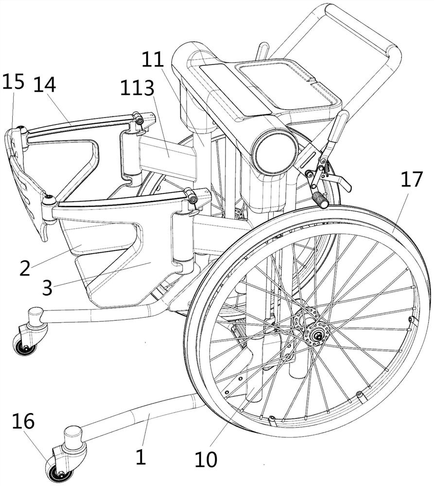
[0123] The distinguishing technical features of this embodiment are: Figure 4 Shown, an embodiment of wheel group mechanism, the diameter of front wheel 17 and trailing wheel 16 is identical;

[0124] When the diameter of rear wheel 16 and front wheel 17 is identical, most preferably diameter is between 4-20cm, promotes by the U-shaped push handle of seat frame 1 top;

[0125] The specific complete implementation example is as follows:

[0126] A convenient seat, such as figure 1 As shown, it includes a seat frame 1 and a seat structure. The seat frame 1 includes two frame shafts, and each frame shaft in the two frame shafts includes a vertical part and a horizontal part that are fixedly connected together at one end.

[0127] The seat structure can be rotated and opened and closed in the horizontal direction, and is connected to the vertical part. The seat structure includes a seat surface placed horizontally and facing each other, and chair handles 3 arranged on both side...


PUM


Abstract

The invention discloses a sitting device convenient to sit, which comprises a sitting device frame and a chair structure, the sitting device frame comprises two frame shafts, and each of the two frameshafts comprises a vertical part and a transverse part of which one ends are fixedly connected together; each transverse part is provided with a wheel set mechanism for moving the sitting device; thechair structure can be connected to the vertical parts in a rotational opening and closing manner in the horizontal direction, the chair structure comprises chair surfaces which are horizontally arranged and opposite to each other and chair handles arranged on two sides of the chair surface, and the chair handles are connected to the vertical parts in a lifting manner; and each vertical part is further provided with a rotary lifting mechanism used for lifting the chair structure, the two rotary lifting mechanisms are driven by at least one driving source, and the chair structure is synchronously lifted through a synchronizing mechanism. According to the sitting device convenient to sit, the wheel set mechanisms and chair mechanisms are correspondingly arranged on the two wings of the movable sitting device frame, the chair mechanisms on the two wings can be opened and closed, synchronous lifting is achieved through the synchronous mechanism, and a user can conveniently get on and offthe sitting device and sit on the sitting device without the help of external force.

Description

technical field [0001] The present application relates to the field of nursing care, in particular to a seat which is convenient for riding. Background technique [0002] For the elderly or patients with limited mobility, especially those with limited mobility in the lower limbs, such as the elderly with weak lower limbs or patients who have just undergone surgery on the lower limbs, they can only lie on the bed every day, and they may be able to sit up on the bed with the help of handrails, etc. The movement of the elderly or patients with limited mobility in the lower limbs (hereinafter referred to as the user) usually needs to be completed by means of a movable seat, such as a wheelchair. Wheelchairs are the most commonly used type of seating to help people with reduced mobility in their lower limbs. When a user uses a traditional wheelchair, he or she generally needs help from others to sit on the wheelchair, and then turns the wheels of the wheelchair by himself or is ...

Claims


Application Information

Patent Timeline
Patent Type & Authority Applications(China)
IPC IPC(8): A61G5/00A61G5/10A61G7/14
CPCA61G5/00A61G5/1059A61G7/1013A61G7/1046A61G5/1091
Inventor 顾永辉吴昌琳程建军
Owner 上海慈通科技有限公司
Why Eureka
Try Eureka