Supercharge Your Innovation With Domain-Expert AI Agents!

Anti-loose clamping chuck structure

A technology of loose clamping and clamping, which is applied in the field of clamping structure of anti-loosening clamping, and can solve problems such as damage and collapse of the clamping clamp

Active Publication Date: 2021-02-23
OUNI WORLD IND CO LTD
View PDF6 Cites 1 Cited by
  • Summary
  • Abstract
  • Description
  • Claims
  • Application Information

AI Technical Summary

Problems solved by technology

[0004] However, although the above-mentioned patent can rotate the rotating cover in the direction of locking (LOCK) to control the brake block to block the gear ring of the central shaft and prevent loosening, it is found in practice that the operator often replaces the tool. During the process, if you forget to rotate the rotating cover in the direction of UNLOCK until it is unlocked first, then use a tool to dismantle the rear sleeve, and the rear sleeve is forcibly rotated, resulting in the collapse of the brake block and the gear ring in the stuck state. bad, causing the entire chuck to be damaged

Method used


Image

  • Anti-loose clamping chuck structure
  • Anti-loose clamping chuck structure
  • Anti-loose clamping chuck structure

Examples


Embodiment Construction

[0032] In order to illustrate the central idea of ​​the present invention in the column of the above-mentioned content of the invention, it is now expressed in specific embodiments. Various objects in the embodiments are drawn according to proportions, sizes, deformations or displacements suitable for illustration, rather than drawn according to the proportions of actual components, which are described first.

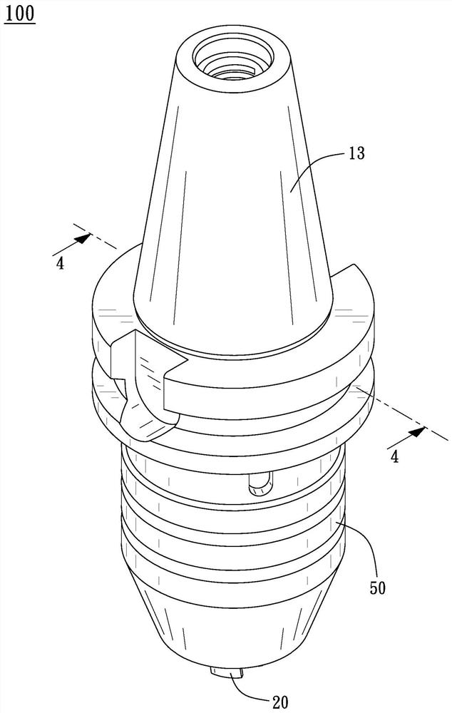
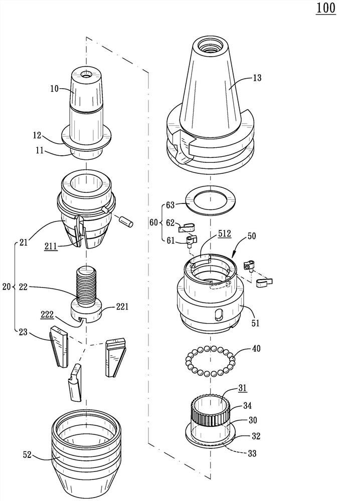
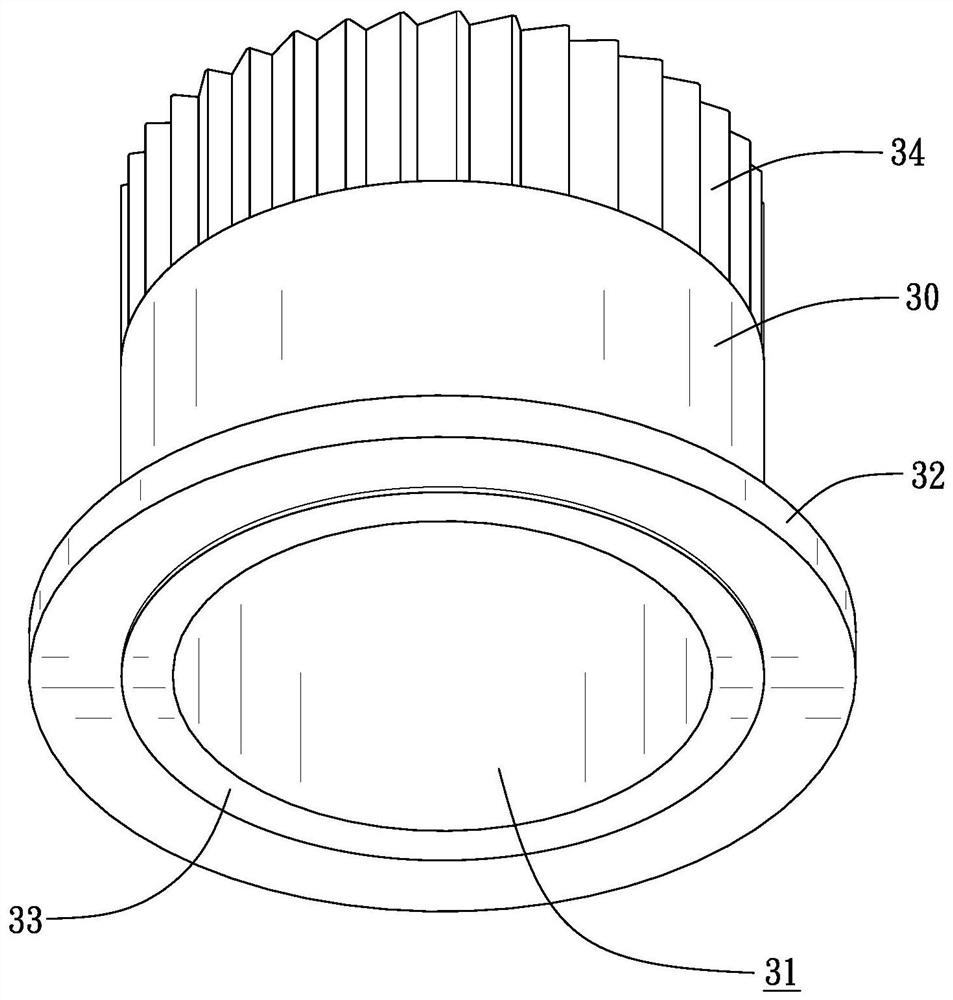
[0033] see Figure 1 to Figure 11 As shown, the present invention provides a chuck structure 100 for anti-loosening clamping, which includes a connecting shaft 10, a clamp 20, a damping member 30, a plurality of rollers 40, a pivot sleeve 50 and a one-way mechanism 60, of which:

[0034]The connecting shaft 10 has an end portion 11 and a first disc portion 12 adjacent to the end portion 11 , and the first disc portion 12 is arranged around the connecting shaft 10 in a radial direction. In this embodiment, the connecting shaft 10 is connected to a handle 13 at an end d...


PUM


Abstract

The invention provides an anti-loose clamping chuck structure. The anti-loose clamping chuck structure comprises a connecting shaft, a clamp, a damping piece, a plurality of rollers, a pivoting sleeveand a one-way mechanism. The connecting shaft is sleeved with the pivoting sleeve in a pivoted mode, and the pivoting sleeve is connected with the clamp and can rotate; when the pivoting sleeve rotates to enable the clamp to clamp a tool, disc parts are pressed in advance at an abutting position to form friction resistance, then the two disc parts are screwed again, the two disc parts are pressedand deformed at the position with a gap, secondary pressing is achieved, and the friction resistance is improved. The one-way mechanism is connected between the pivot sleeve and the damping piece ina one-way driving mode, and only when the pivot sleeve rotates in the unscrewing direction, the damping piece is driven by the one-way mechanism to rotate, so that the secondary packing force and thepre-packing force are released in sequence till the friction resistance is relieved, and the effects of easy drive and high clamping force when a tool is clamped are achieved.

Description

technical field [0001] The invention relates to a collet used for a processing machine tool, in particular to an anti-loosening clamping collet structure. Background technique [0002] The collet of the tool bar of the existing machine tool is rotated by the rear sleeve to drive the jaws to generate a clamping torque for the tool. After the rear sleeve presses the ball on the connecting seat, the connecting seat and the body It is generated by contacting two opposite faces, and the torque reaches the maximum at the moment of compression. However, although pressing with face contact can produce a tight effect, the vibration of the machine tool operation or the reverse moment of inertia generated at the moment of stop after the rapid rotation of the tool bar may cause the connection seat or the body to loosen, resulting in resistance. Then the pressing failure will cause the tool to loosen on the jaw, so further improvement is needed. [0003] Such as China Taiwan Patent Ann...

Claims


Application Information

Patent Timeline
Patent Type & Authority Applications(China)
IPC IPC(8): B23Q3/00
CPCB23Q3/00
Inventor 林原禾林昆贤林昆葆
Owner OUNI WORLD IND CO LTD
Features
  • R&D
  • Intellectual Property
  • Life Sciences
  • Materials
  • Tech Scout
  • Unparalleled Data Quality
  • Higher Quality Content
  • 60% Fewer Hallucinations
Learn More